When the µSCOPE project was well underway, it was clear to me that
my next project just had to be
a miniature version of the classic
PONG game. The PONG game was invented back in 1966 by Ralph Baer [1,2].
In the seventies the game became very popular and I remember that
as a child I was completely fascinated by it. We had a later version
at home, and on
inspection it appeared that there was only one 40 pen IC in it, how did
they do it ? In 1973 the Dutch electronics magazine Elektuur (Elektor
for the rest of the world) organized a circuit design contest.
Electronics enthusiasts where invited to submit their favorite
circuit designs. Via a complicated set of rules, which I have never
understood, a calculation of the costs for the components that were used
was made. Part of the sum was given to the designer, the rest
was given to the charity fund: "Aktion Sorgenkind".
The first price was a homebrew version of PONG by the youthful
B Lübcke from Kiel, Germany [3]!
With nine TTL 74121 type one-shots and a handful of logic gates the
clever designer was able to make a real functional tennis game
on the TV. I was amazed how simple it all could be!
The µPONG game works essentially the same as the original
1966 design. However, in the PIC version the hardware one-shots have
been replaced by software delays. A number of microcontroller
based PONG games have been published or posted on the internet [4,5].
This µPONG version is so far the smallest, using only an 8 pin
PIC processor, and is the only one to use two potentiometers for the
bat controls, just as the original PONG game. In Fig. 1 the circuit
diagram of the µPONG is given. Although the circuit is pretty
simple, it does contain some special tricks which will be explained
in the text below.
Figure 1 Circuit diagram of the µPONG
Obviously the µPONG program contains many elements from the
µSCOPE program. The line dispatcher concept is directly copied
from the µSCOPE as well as the implementation of the asynchronous
part and the routines that display the characters. If you are interested
in finding out how the µPONG program works, the µSCOPE
page will be a good start. Some of the special tricks and features of
the µPONG program will be explained on this page. I admit it,
the µPONG program is not one of my finest pieces of programming.
Nevertheless, the assembler source is available for downloading.
Unfortunately it is not so well documented as the µSCOPE
source.
Sorry, this is a PAL only version! I do not think I will make an NTSC
as well. This one has given me enough headaches already. It is time for
something different now.
a 1.5 bit video output
For the generation of the video signal commonly 2 outputs are used.
One for the video signal and one for the synchronization pulses.
The µPONG project almost found a premature end when I discovered
that I was short of one output.
Of the 8 pins from the 12f675, 2 pins are needed for power, 2 pins are
connected to the crystal and 2 pins are used to read out the potentiometers.
This leaves 2 pins. To my surprise I learned from the datasheet that
pin 4 (GP3) can only be used as a digital input. This leaves just one
general purpose I/O pin that can be configured as output.
Fortunately, this one I/O pin represents more than 1 bit! When the pin is
configured as an output it exactly represents one bit (high or low). But
it can have a third state namely high impedance or input. So each I/O
in reality represents 1.5 bit! A small circuit translates the three
states of GP0 (low, high and high impedance) into a valid composite
video signal. To understand how it works, we will build the circuit up
step by step.
Figure 2
We start with two resistors connected as indicated in Fig. 2. With these
kind of circuits it is important to realize that the video input of
the television set
has a termination resistance of 75 ohm to ground. By proper choice
of R1 and R2 it is possible to translate +5V on the GP3 to 1.0 V on the
video input (white) and the high impedance state to 0.3V (black).
However, 0V on GP3 will not result in 0V on the video input (sync. level)
since there will be a voltage drop over R1.
Figure 3
This can be remedied by shunted R1 with diode D1 (Fig. 3).
The idea is that D1
pulls the video output to ground when GP3 is low. This idea would work
if D1 was ideal. In reality D1 will have a voltage drop of ca. 0.6V
when forward biased.
Figure 4
By placing a second diode D1 in series with the video output, an
identical voltage drop is introduced (Fig. 4).
This level shifter will cause
the video output to become 0V when GP3 is 0V.
Figure 5
There is only one snag. The MOS transistors of the 12ff675 that switch the
output high and low are also not ideal in the sense that they have
an on-resistance, which is greater than zero. In other words when
the output is sinking current the output voltage will be no longer 0V.
By adding a second level shifter diode this
voltage drop is compensated (Fig. 5).
Table 1 Possible states of the video output with corresponding setting
of IO registers.
Table 1 summarizes how bit 0 in the output register GPIO and the output
control register TRISIO need to be programmed for a white, black or sync.
level. Unfortunately, these registers reside in different memory banks.
Figure 6 gives the pieces of assembler code required to switch the video
output from one level to another. Since the output only switches to and from
the sync. level from black, the number of possibilities is limited to 4.
Figure 6 Assembler code required to switch the video output from one state
to another.
The game field
In some microprocessor pong games the screen is organized as a graphic
display with rather large pixels [6]. The internal RAM memory in that case
is used as a bit mapped video memory. The advantage is that the synchronous
routines only have to read out the memory and display the contents on the
screen. The asynchronous part of the program writes the ball and the bats
in the memory.
There are two drawbacks to this method. First of all the resolution
is somewhat limited. Secondly, and more important the 12f675 only has 64
bytes of RAM memory. By far not enough to make any kind of decent
graphical display. In µPONG therefore a different approach is used.
Like in the original PONG game programmable timers are used to determine
the size and the location of the objects. The difference of course is that
in the original PONG game hardware timers were used whereas in the
µPONG game software timers are used. These timers are only used for the
horizontal sizes and locations by the way,
in the vertical direction simply line counters are used.
Figure 7 Interlacing of the bat and ball frames.
A difference with hardware timers however is that hardware timers can trigger
each other almost instantaneously. In software that is impossible. Always a
number of instructions are required to fill counters set bits etc. The
time that these instructions take make that it is impossible for the ball
to really touch the bat. The solution to this problem is illustrated in
Fig. 7. During the odd lines, the bats and the centre line are displayed.
The ball is displayed during the even lines. The lines are so closely spaced
that it appears to be one image on the television screen.
The line dispatcher calls the "line_game" routine 108 times to generate the game
field. The "line_game"routine actually generates two lines: an odd line with the
bats and the centre line, and an even line with the ball. So in total the image
field consists of 216 lines. The line routines receive the bat y coordinates
through Y_L and Y_R and the ball position through X_BALL and Y_BALL.
How the bats are moved
Thanks to the on-chip AD converter and the analog multiplexer it was possible
to use two potentiometers for the control of the bats. Since there were no IO
pins left for the "fire" buttons a special trick was used to also use the analog
inputs for the potentiometers for the "fire" buttons. Although the AD converter
has a resolution of ten bits only the 8 most significant bits are used. If the
ADFM flag in ADCON0 is cleared, these higher 8 bits reside in the ADRESH register
(see 12f675 datasheet). Because the game field consists of only 216 lines, only
216 of the possible 256 codes are used or a voltage range of 0 to 4.21V
(assuming a 5V power supply). P3 and
P4 are adjusted so that P1 and P2 exactly this voltage range. They are adjusted
so that by turning the potentiometers to their extreme positions, the bats cover
the complete image field.
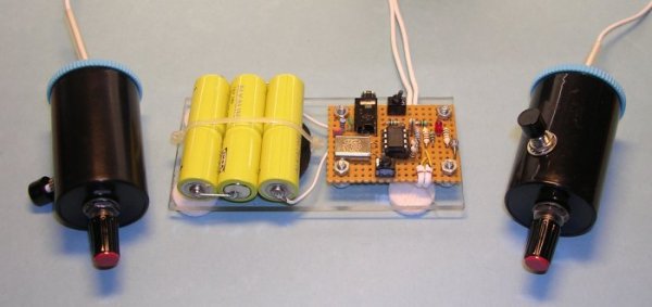
Figure 8 complete µPONG with control units
Pressing the "fire" buttons directly connects the
analog inputs of the processor to 5V. This is detected by the "line_AD" routine
which processes the analog inputs. If ADRESH reads FFH it is assumed that the
"fire" button was pressed. Note that since the lowest 2 bits of the AD converter
are ignored this will give a noise margin of about 0.1V to compensate for
contact resistances etc. Both buttons are debounced by debounce counters
DEBNC_L and DEBNC_R. Resistors R5 and R6 limit the current when the fire button
is pressed when the potentiometers are in their 0V position.
Pin 5 is also used as output (see Beep, beep section) so R4 limits the current
through pin 5 in this case. R3 was just added for symmetry.
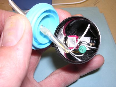
The control units are housed in two old photo film containers and I use some flexible
cable with two shielded wires to connect them to the processor (Figs. 8 and 9).
Figure 9 interior of the control units made in two old
photo film tubes.
The "line_AD"routine additionally keeps track of the direction of movement
of the bats, and of their speed. The direction of movement is used during
serving off the ball so that the payer can chose the direction the ball is going.
It was my original intention to use the speed of the bat to implement
effect, but I did not get round to it.
Figure 10. Example illustrating the decision procedure used to see if the
bat is "on or off".
The "line_game" routine takes care of the actual displaying of the bats on the screen.
A standard implementation of this feature would require quite some calculations: the
y coordinate of the bats needs to be compared with the line number, the height of the
bats needs to be taken into account etc. etc. In short a lot of instructions, jumps
and headaches. In stead I used a simpler trick, that only requires that the bat has
a length that is a power of 2 (2,4,8,16 etc). The trick is explained in Fig. 10. Figure 10
gives 4 examples for 4 different AD conversion results. The first thing that is done is
that the height of the bat-1 is added to the AD conversion result.
In this example the height of the bat is taken to be 4, so 4-1=3 is added to the AD result.
Next this number is decremented for every new line. Now, the criteria to turn the pixels
of the bat on is to check if all but the lowest 2 bits of this number are 0! If of course
the bat is longer less bits need to be checked. Although this trick may seem
complex, it really requires only a few instructions and what is more important a minimal
amount of conditional jumps which are always cumbersome in synchronous programs.
How the ball moves
The variables X_POS and Y_POS contain the location of the ball on the screen.
Y_POS is actually a line number and X_POS a delay (argument for the delay routine).
The first thing that "line_compute" does is to check if the ball is moving (Listing 1).
If so, the routine "move" is called. In fact move is called twice since it
was found that this gave a much smoother ball movement. At a certain moment
during the writing of the program I encountered a very strange error.
After searching for 2 days! I found that it was due to a subroutine
stack overflow. I had nested too many routines. For this reason the move
routine was included into "line_compute".
subroutine line_compute
   if (ball is moving) then
      call move
          call x_move
             if (ball moves left to right) then
                call x_L2R
                    call hit
                    end hit
                end x_L2R
             else
                call x_R2L
                    call hit
                    end hit
                end x_R2L
             end if
          end x_move
          call y_move
          end y_move
      end move
      call move
          .
          .
      end move
   end if
end line_compute
Listing 1
In "move" the movement in the x-direction and y-direction are dealt with
separately. Routine "y-move" takes care of the y-movement. Counter
Y_SPEED is used to regulate the speed. It is decremented and when it reaches zero,
Y_POS is adjusted. Depending on the direction (top-2-bottom or bottom-2-top)
as indicated by flag T2B, Y_POS is incremented or decremented. When the
ball reaches the edges of the field, T2B is inverted and we hear a beep.
Figure 11. Movement of the ball caught by the camera
The movement in the x-direction is done in routine "x-move". Similar to the
"y-move" routine, counter X_SPEED is used to regulate the speed. But now
depending on the direction indicated by flag L2R either routine "x_L2R"
or "x_R2L" is called. As you might have guessed these routines take
care of the left-2-right and right-2-left movement respectively.
These routines either increment or decrement X_POS. Next, X_POS is
compared to the X position of the bat. If they are equal, routine "hit"
checkes if the ball touches the bat. If so, the direction of the ball
is inverted. Finally, the routine checks if the ball has left the field
(ball is out).
The asynchronous main program controls the game and takes care of
the user interface. It basically sets the ball position and direction,
and sets the GO flag when the fire button is pushed. This will start
the movement of the ball. The main program now waits until the ball is
out, indicated by either R_OUT or L_out being set.
Beep, beep ....
Halfway through the programming of the µPONG game I decided to add
an audio output. A Pong game without the characteristic "beep" just
wouldn't be realistic! The problem was that I didn't have any outputs
left. In fact I was already short on outputs for the video output
signals (see section a 1.5 bit video output).
The answer to the problem was found in the fact that the bat potentiometers
are only read once every frame (20 ms). The AD conversion only takes
a few dozen or so microseconds. So the trick I used was to configure
pin 5 as an output for most of the time, and to switch it to an
analog input only just long enough to sample the potentiometer.
There is a penalty: when pin 5 is switched from output to input,
its potential will assume the potential of the potentiometer instead
of a well defined 1 or 0. This will add a 50 Hz interference to the
audio signal. Since it is only switched as input for a very short time
relative to the frame rate, the energy contents of the 50 Hz interference
will be relatively small, but audible nevertheless. A small filter
consisting of C2, C3 and R6 eliminates the 50 Hz signal as much as possible.
Figure 12 Flow diagram for the beeper code.
In the program code the beep is implemented by a 2 byte counter: BCNT_1 (lower
order bits) and BCNT_2 (higher order bits).
When the main program issues a beep, it appropriately sets the BEEP flag.
When the beep flag is set, the counter is decremented once every line (Fig. 12).
Directly after every increment bit 2 from BCNT_1 is copied to the output (pin 5).
This will cause a beep of exactly 1953 Hz. When the counter reaches zero the beep
is over. The beep code was combined with the code for the generation of the horizontal
sync. pulse in routine "H_sync".
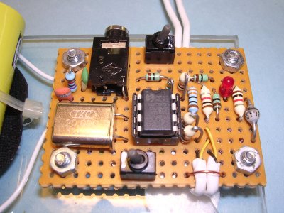
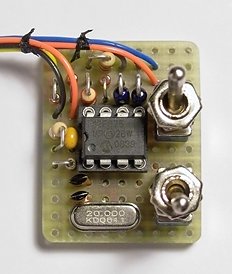
Build your own µPONG game
The µPONG game is so simple that it should not be a problem for
somebody with a little experience to build it on a piece
of breadboard. Figures 8 and 13 illustrate how the final circuit
can look like. For the connection of the µPONG circuit to
the TV, I use a cable that is supplied with some monitors to connect
the audio output of the PC to the build in speakers in the monitor.
It has on the one side a 3mm phone jack and on the other side two tulip
connectors. The circuit uses only 10 mA so that 3 AA cells can be
used for power supply. I used a "Tait style" programmer to program the
12f675, but of course you can use any suitable programmer.
At the bottom of this page you can download a zip file containing
the circuit diagram, the assembler source file and the assembled
hex file. Before you start please be aware that this game is only
suitable for PAL televisions (625 lines) and not for NTSC sets!
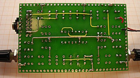
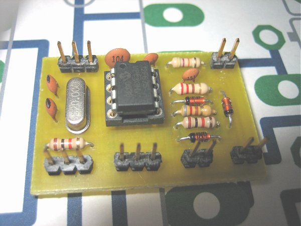
Figure 13 Detail of the µPONG circuit board.
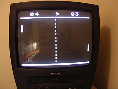
Playing the game
The µPONG game can be played with one or two players.
The position of S3 during power up determines if it is a one
or two player game. In the one player mode, the processor
operates the other bat. Needles to say that the processor
is a very good player. Once the selection for one or two players
is made during power up, S3 is used to select "beginners" or
"experienced" mode. The ball speed is higher in the last one.
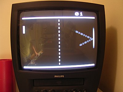
An arrow in the middle two digits indicates the player
which about to serve. The game continues until one of the two
players reaches score 50. The speed of the ball is increased
when one of the two players reaches a score of 10 and again at
20 etc. When one of the two players has won, the only way to
reset the game is to switch it off and on. Crude, but effective!
Figure 14 The left player is about to serve. By the way you can see
a reflection of me while taking the photograph.
The Jet-Net version
Jet-Net stands for "Jongeren en Technologie Netwerk Nederland" (Youth and Technology
Network the Netherlands).
Jet-Net was set up in 2002 between - at that time - five major companies, the economics and educations ministries, Dutch employer's organizations and intermediary organizations in the education sector [7]. Its prime aim is to stimulate increased interest among high school students to pursue their studies and future career in Science and Technology.
At the moment it has 25 active industrial companies participating as well as 125 high schools. The program includes workshops at school as well as in the companies, excursions, expert meetings, host teaching and theme projects.
Philips Research is heavily involved in the Jet-Net program. Among the many activities
Philips research organizes within the program is an electronics projects were high school
students build an electronic sensor circuit with an LED bar read-out. After proper tuning
the idea is to use this circuit as a simple lie detector. The project consists of
host teachings by Philips experts at high schools. The first lesson is spend on theory.
During the second lesson the students actually build the sensor circuit on a specially
designed printed circuit board.
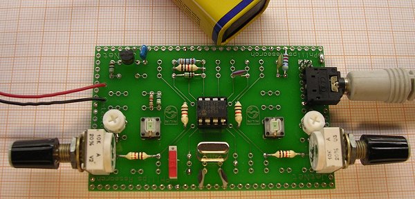
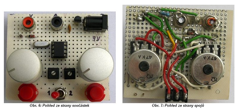
Figure 15 The µpong game built on the universal Jet-Net printed circuit board.
The circuit board is designed to hold a 16-pin DIL IC and several passive components.
It appeared that this PCB was also ideally suitable for the µpong game.
To demonstrate to the students that even with relatively simple means interesting
circuits can be made the I built a µpong game on one of the Jet-Net PCBs.
Figures 15 and 16 depict the front and rear side of the circuit. Since this circuit had to be operated from a 9V battery, I included a low-current 78L05 voltage regulator.
Figure 16 Wiring on the rear-side of the Jet-Net PCB.
Figure 17 A possibly even smaller version of uPong by Gerard Bolten.
 a miniature version of the classic
PONG game. The PONG game was invented back in 1966 by Ralph Baer [1,2].
In the seventies the game became very popular and I remember that
as a child I was completely fascinated by it. We had a later version
at home, and on
inspection it appeared that there was only one 40 pen IC in it, how did
they do it ? In 1973 the Dutch electronics magazine Elektuur (Elektor
for the rest of the world) organized a circuit design contest.
Electronics enthusiasts where invited to submit their favorite
circuit designs. Via a complicated set of rules, which I have never
understood, a calculation of the costs for the components that were used
was made. Part of the sum was given to the designer, the rest
was given to the charity fund: "Aktion Sorgenkind".
The first price was a homebrew version of PONG by the youthful
B Lübcke from Kiel, Germany [3]!
With nine TTL 74121 type one-shots and a handful of logic gates the
clever designer was able to make a real functional tennis game
on the TV. I was amazed how simple it all could be!
a miniature version of the classic
PONG game. The PONG game was invented back in 1966 by Ralph Baer [1,2].
In the seventies the game became very popular and I remember that
as a child I was completely fascinated by it. We had a later version
at home, and on
inspection it appeared that there was only one 40 pen IC in it, how did
they do it ? In 1973 the Dutch electronics magazine Elektuur (Elektor
for the rest of the world) organized a circuit design contest.
Electronics enthusiasts where invited to submit their favorite
circuit designs. Via a complicated set of rules, which I have never
understood, a calculation of the costs for the components that were used
was made. Part of the sum was given to the designer, the rest
was given to the charity fund: "Aktion Sorgenkind".
The first price was a homebrew version of PONG by the youthful
B Lübcke from Kiel, Germany [3]!
With nine TTL 74121 type one-shots and a handful of logic gates the
clever designer was able to make a real functional tennis game
on the TV. I was amazed how simple it all could be!