Convert your 300 V utracer3 into a 400 V uTracer3+ with these step-by-step conversion instructions.
Ronald Dekker
In this section the step-by-step conversion of a 300 V uTracer3 into a 400 V uTracer3+ will be described. This conversion consists of two parts: the installation of the new GUI, and some hardware modifications. For the hardware modifications a small kit containing all the necessary components is available from my “How to Order” page.
Installation of the new GUI.
For the 400 V uTracer3+ hardware the latest version of the GUI (version 3.11) needs to be installed. The installation of the new GUI is very simple! Since you already will have an older version of the GUI running, all the necessary auxiliary OCX components and dll files have already been installed and registered. Installation of the latest GUI is now only a matter of installing a new executable:
Go to the download page and download the
“GUI v3p11 exe only” compressed zip file, and save it to a convenient location e.g. the desktop.
Unpack (unzip) the zip file to obtain the uncompressed executable (Application).
Locate the folder in your program files containing your old GUI. In my case it was in: C: --> Program Files (x86) --> uTracer_3p10.
Move or copy the uncompressed executable into that folder. Do not delete the old GUI. If needed they can work in parallel. Running one does not affect the other.
Right click with your cursor on the 3p11 executable and create a shortcut.
Move the shortcut to your desktop.
Start the GUI 3p11 by double clicking the shortcut.
If everything is ok the GUI 3p11 will now start and give a message that a new calibration file has been generated based on the calibration data of the previous GUI version.
Click the “Cal” button to open the calibration form.
Check if the calibration values have indeed been copied.
Select the 400 V uTracer 3+ version (see Fig. 1).
Save the calibration file. This will send the calibration form to the back because the GUI was restarted. Bring the calibration form to the front again and close it.
Close the GUI, restart it, open the calibration form and check if the correct version has indeed been stored correctly.
The GUI 3p11 is now ready for use.
Figure 1 The uTracer version can be selected and stored in the new calibration form in the GUI.
Hardware modifications.
Figure 2 shows the complete circuit diagram of the uTracer3+ hardware. The components which have been changed are high-lighted in red.
Figure 2 Complete circuit diagram of the 400 V uTracer3+
In the following a step-by-step modification of the hardware will be described. Changing components on a heavily populated PCB is never a pleasant task which is why I have tried to figure out a procedure which makes life a easy as possible. From the circuit diagram it can be seen that some resistor values have been changed with respect to the uTracer3+. In all cases the new resistances will be lower. Rather than removing the old resistor, in most cases I have chosen to lower the resistance by placing a second resistor in parallel to the original resistor on the bottom side of the PCB. This eliminates the need for a messy removal of the original resistor. In some cases completely new components had to be added, and the placement of these components on the bottom side of the PCB could not be avoided. However, there will undoubtedly be people who prefer to simply exchange the resistors where possible. That is why in the conversion kit I intend to supply also the resistors for direct replacement have been included.
Removal of the 100 uF / 400 V caps
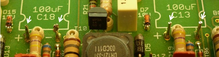
Remove the 400 V caps C13, C18 by simply clipping the wires. Leave 4 to 5 mm of wire sticking out of the PCB. The new caps will be soldered to these wire ends. This will be the last step in the conversion process so that for now we have an easier access to the other components, and the board weighs less.
Old 100 uF / 400 V removed.
Removal of C15 and C20
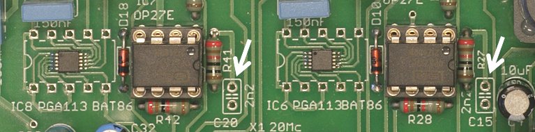
Remove the 2.2 nF capacitors C15 and C20. The easiest thing is to just clip one of the leads of the capacitors and leave them in place. In this way it is always possible to simply reconnect them. Preferably clip the lead which is furthest away from the PIC processor. Note that C15 and C20 are not replaced by another capacitor!
C15 and C20 removed.
Replace T12 and T17
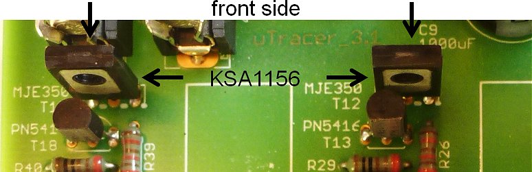
The MJE350 transistors in the high voltage switch need to be replaced by two KSA1156 transistors with a higher breakdown voltage. Also here it is possible to simply cut the leads of the MJE350 transistors and solder the KSA1156 transistors to the part of the leads remaining in the PCB. The pinning and orientation of the KSA1156 transistors is identical to the MJE350’s.
T12 and T17 replaced by KSA1156 transistors.
Add C36 and C38
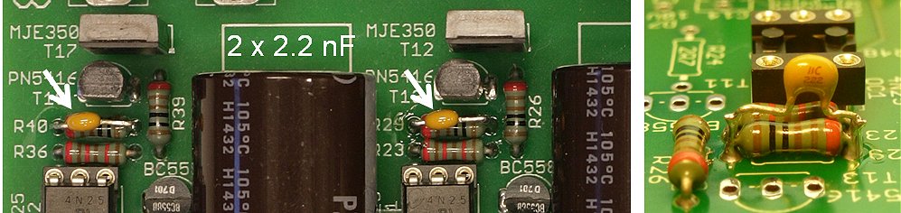
C36 and C38 are two small 2.2 nF capacitors that are in parallel to resistors R40 and R29. Since we will be already adding a number of resistors to the backside of the PCB, I recommend to solder C36 and C38 directly over the resistors on the frontside of the PCB (see photograph below).`
C36 and C38, two 2.2 nF capacitors are soldered directly over R29 and R40. Note that the photograph on the right was taken at an earlier stage during the construction when not all the components on the board were placed yet.
Add C35 and C37
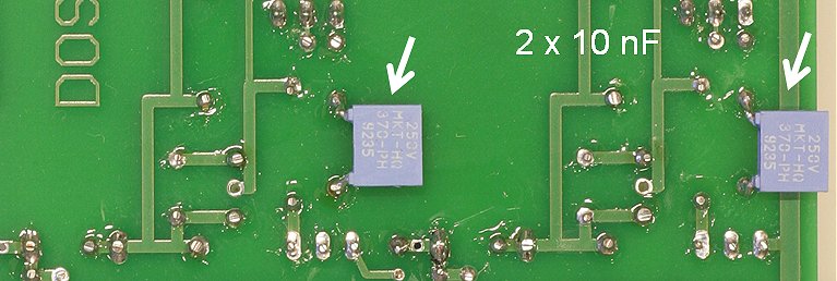
Stricktly spoken C35 and C37 have nothing to do with the 400 V conversion. They were added to improve the switching speed of T10 and T15 which in some cases may result in a more accurate “Quicktest.” In the last series of uTracers these capacitors were already added to the kit, but in the earlier series it will be missing. The two 10 nF capacitors are soldered in parallel to R21 and R34 on the backside of the PCB on the locations indicated in the figure below.
C35 and C37 are soldered over R21 and R34 on the backside of the PCB.
Modify R18 and R32
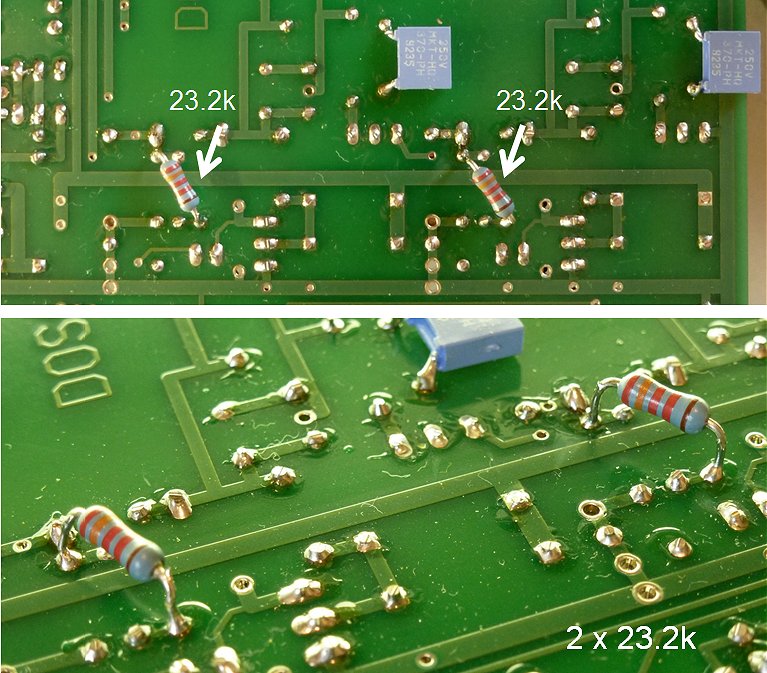
In the 300 V version of the uTracer, R18 and R32 have a value of 6k8. For the 400 V uTracer3+ this value needs to be lowered to 5k23. The simplest way to do that is by adding a 23k2 resistor in parallel to the existing 6k8 resistor. The photograph below shows the location on the bottom side of the PCB where these resistors need to be placed. Alternatively, the original resistors van be removed, and replaced by 5k23 resistors (also supplied with the conversion kit).
Modification of R18 and R32 by placing two 23k2 resistors in parallel to the original 6k8 resistors (top view and side view).
Replace R46 and R48
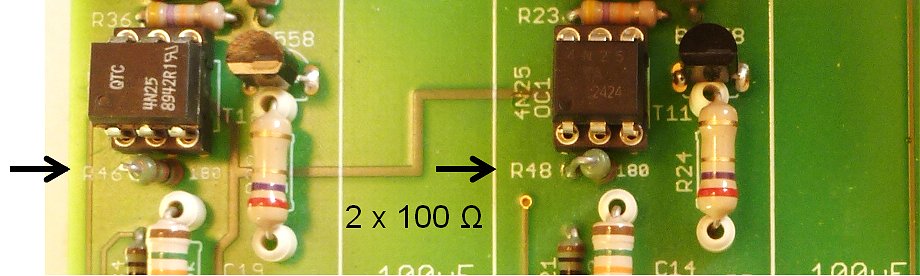
R46 and R48 are the only two resistors where I recommend replacing them completely. Since they are mounted in a vertical position, it is quite easy to get hold of them with a pair of tweezers and remove them without damaging the PCB or other components. They need to be replaced by resistors of 100 ohm.
Replace R46 and R48 by 100 ohm resistors
Add R51 and R52
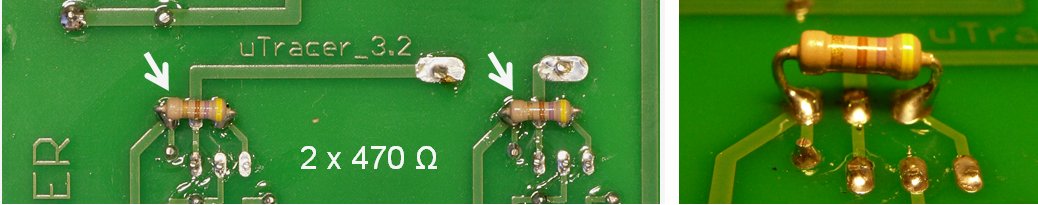
R51 and R52 are also “new” to the circuit. These 470 ohm resistors help “discharging” the emitter base junction of the HV switch transistor. They are placed on the backside of the PCB over the two outer pins of the KSA1156 transistors (T12, T17)
R51 and R52 are 470 ohm resistors over the outer pins of the two KSA1156 transistors.
Modify R23 and R36
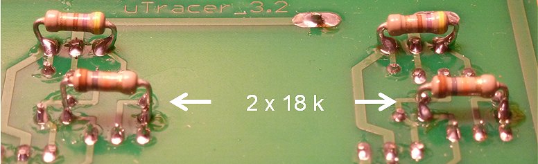
The value of R23 and R36 has to be decreased from 47k to 12.1k. This is done by adding an 18k resistor in parallel to the resistors on the backside of the PCB. Purist will notice that this only lowers the resistance to 13k, but that is close enough. I added two 12k1 resistors to the conversion kit for people who insist on replacing the resistors.
Modification of R23 and R36 by placing two 18k resistors in parallel to the original 47k resistors.
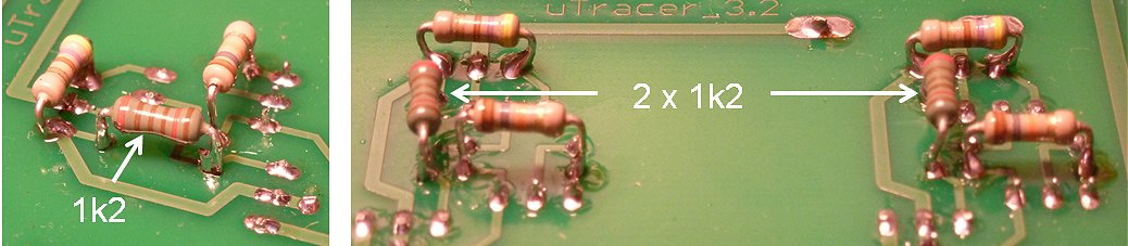
Modify R26 and R39
Similarly the value of R26 and R39 is decreased from 12k to 1k by adding a 1k2 resistor in parallel. I added two 1k resistors to the conversion kit for people who insist on replacing the resistors.
Modification of R26 and R39 by placing two 1k2 resistors in parallel to the original 12k resistors.
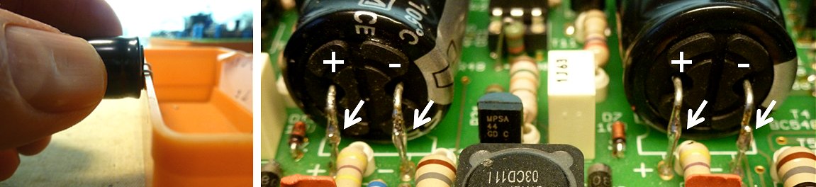
Replace High voltage caps C13 and C18
Finally the high voltage reservoir caps C13 and C18 are replaced by 100 uF / 450 V types. The easiest way to bend the leads nicely in parallel in a 90 degree angle is shown in the figure below. Note the correct polarity of the caps before bending the leads.
Replacing the high voltage reservoir caps for 450 v types completes the conversion.
Calibration
A small calibration of the output voltages is necessary:
Connect a DVM between the cathode connection of the uTracer and the positive terminal of the 100 uF / 450 V anode reservoir capacitor (C18).
run the first measurement type “I(Vg, Va) with Vs and Vh constant” with Va = 400 V and Vs = 400 V.
Read the actual anode voltage from the DVM.
Open the calibration form.
Adjust slider “Va gain” to the left if the voltage was too high, to the right if it was too low.
Repeat from step 2 until the voltage is 400 V.
Connect the DVM between the cathode connection of the uTracer and the positive terminal of the 100 uF / 450 V screen reservoir capacitor (C13).
Repeat steps 2-6, now adjusting slider “Vs gain”
Save the calibration form
Component list
The table below gives lists the components needed for the conversion of the utracer3 into the uTracer3+. The working voltage of the capacitors is not relevant and the resistors are 1/4 or 1/8 Watt type. I am offering a small conversion kit which includes all the components listed below: