Christmas 2010
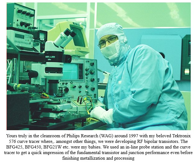 When I was still heavily involved in the development of RF bipolar transistors at Philips Research, transistor curve tracers and parameter analyzers were instruments that were daily used to characterize transistors. A curve tracer typically would be used to get a first impression of the functioning of a transistor, while a parameter analyzer would be used to characterize a device in detail and with great accuracy.
Parameter analyzers are sophisticated pieces of equipment basically consisting of several programmable voltage / current sources and meters. They are used to measure the I-V characteristics of semiconductor devices, often down to pico-amp levels! Wouldn’t it just be great to have such an analyzer for tubes? Thinking about the construction of such a tube-analyzer, my enthusiasm quickly subsided. In a straightforward construction it would involve several heavy-duty high-voltage power supplies with associated transformers, cooling stuff, ventilators etc. Not really my cup of tea!
When I was still heavily involved in the development of RF bipolar transistors at Philips Research, transistor curve tracers and parameter analyzers were instruments that were daily used to characterize transistors. A curve tracer typically would be used to get a first impression of the functioning of a transistor, while a parameter analyzer would be used to characterize a device in detail and with great accuracy.
Parameter analyzers are sophisticated pieces of equipment basically consisting of several programmable voltage / current sources and meters. They are used to measure the I-V characteristics of semiconductor devices, often down to pico-amp levels! Wouldn’t it just be great to have such an analyzer for tubes? Thinking about the construction of such a tube-analyzer, my enthusiasm quickly subsided. In a straightforward construction it would involve several heavy-duty high-voltage power supplies with associated transformers, cooling stuff, ventilators etc. Not really my cup of tea!
I readily confess that it was during a less inspiring moment of the 2010 Christmas lecture in our church that the idea popped in my mind that it all could be done in a much simpler way by using a pulsed, instead of a continuous measurement!
The idea was to use a simple boost converter that only can deliver a few milliamps of current and let it charge a reasonably sized reservoir capacitor to the desired voltage. Then during a millisecond or so use the energy in these capacitors to bias the tube. By using two of these circuits both the anode and the screen can be biased. When on top of that a microcontroller is used to control the boost converters and to measure the currents, the final circuit could be unbelievably small and handsome!
Back from church the
first experiments
were quickly undertaken. It turned out that a simple boost converter can easily charge a big 100 uF capacitor to 400 V. Needless to say that the remainder of the Christmas holidays was spent on working out the details of the circuit, the uTracer Version 1 was born (on paper).
Start of the uTracer saga
The Version 1 uTracer never made it any further than a circuit diagram and a lot of experiments. The circuit had a lot of problems. In fact at a certain moment it failed, and in the blast that followed, the charge of one of the 100 uF capacitor charged to 400 V destroyed every semiconductor on the PCB. I was lucky my laptop survived!
The disaster set me thinking about an alternative way to construct the circuit. I realized that I could complete do without high-voltage switches!
Pulsing the grid bias
from a negative value below the cut-off point to the set-point value, the tube itself could be used as a switch.
A brilliant idea I thought at the time. This version was fully completed and represents
the Version 2 uTracer.
However, working with it I soon discovered a number of serious drawbacks. Diodes do not have a control grid, so that they couldn’t be tested. Furthermore, the way in which the current was measured – with a high side series resistor and DC blocking capacitor – inevitably resulted in
an unacceptable drift
in the measured currents.
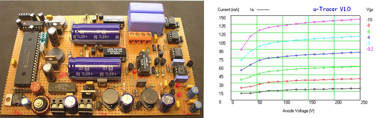
Perfboard prototype of the uTracer2.
The uTracer3 is born
An email with a circuit suggestion from Rene Schmitz
from Germany set me on the trail of an alternative, and much more robust way to measure the currents. If several boundary conditions are satisfied, it is possible to “shift” the current sense resistor from the “high-side” to a position in series with the cathode lead of the reservoir capacitor against ground. Away with drift and all the other problems in the current measurement.
The Version 3 uTracer was born!
After finishing the Version 2 uTracer, I had made
a wish list of features and improvements to be implemented in the uTracer3. I am happy and proud to say that all these items were implemented in the Version 3 which made it a valuable instrument.
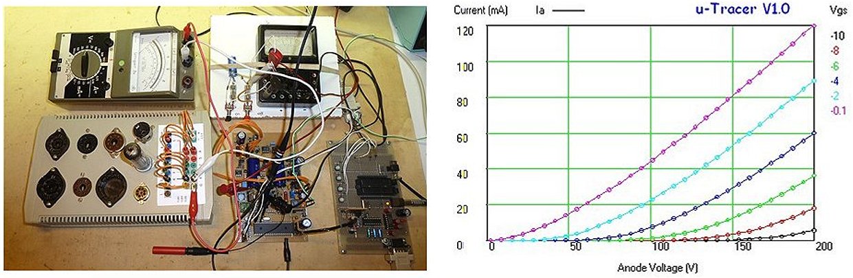
The earliest prototype of the uTracer3 with the first measurement of a real tube (EL84 or 6BQ5) Friday the 27th of February 2012.
This prototype only had one high-voltage channel so that the EL84 was configured as a triode.
Towards a kit
During the project I received many enthusiastic emails from people asking me if I could make a kit, or at least a PCB for the project. At first I really didn’t have an appetite for that. I was busy enough in my professional life to also organize all practical things involved with running a (small) business. Actually my sons persuaded me to change my mind, and my wife offered to take care of all practical administrative matters. I have never sold anything I made for my hobby. Come to think of it, I have never sold anything at all in my life, so it was a completely new experience for me.
The PCB I designed for the uTracer3 kit was the first PCB I designed in my life. At the time I thought it was an incredible gamble to order the PCBs and the components for 10 kits. Everything was new for me, designing and ordering PCBs, Gerber, ordering components at wholesalers like Mouser and Farnel, a website and finally writing a construction manual. The first uTracer “clone” was realized by Roger from Germany who built his own uTracer3 from scratch on perf-board. The first 10 kits were sold in a few months. The success and the positive feedback was encouraging enough to prepare another batch of kits. The “business” grew to such an extent that we registered with the chamber of commerce. I will never forget the face of the man who registered us when he asked us “and what product or service is your business” and my wife, who is officially CEO of “the company” replied: radio tube testers! That was clearly a first for him!
I have the feeling that the interest in radio tube technology is growing every year. Many people who, like me, had electronics as hobby in their youth, and ended up doing something completely different in their adult life, are now retiring. They want to pick up their old hobby, but find modern electronics not easily accessible, so they refer to what they know from their youth. And why not, what can be more rewarding than building an amplifier from these nostalgic glowing technological marvels!
At the updating of this page, there are now 3000 uTracers in service in 69 countries. Who could have believed that!
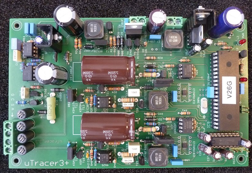
The uTracer3+ has found its way to 2317 homes in 64 countries.
After nearly 15 years it has now been succeeded by the uTracer7.
The hunt for higher voltages
Since the early days of the uTracer project, people have been asking for higher voltages; higher positive voltages for anode and screen, and more negative voltages for the control grid. Most requests came from HAM radio enthusiasts who added also positive grid biases (and hence current measurement) for high-power RF tubes to their wish list.
Most of 2013/2014 was spent on a project coined the uTracer4. The goal was a uTracer for (much) higher voltages, up to 1 kV or even higher. The circuit used pulsed transformers to boost pulses to the required voltages. Although elegant in principle, the practical implementation of the circuit was far from elegant. The main problem was that it was not possible to determine a priori the voltages of the measurement pulses because they depended on the currents drawn. This required iterative schemes which completely ruined the elegance of the whole concept. Despite that I learned a lot about transformers and how they work under pulsed conditions, I finally decided to abandon the project leaving the uTracer4 unfinished.
The problems with the uTracer4 project set me thinking of what could be tinkered with the uTracer3 to push it to somewhat higher voltages. A
thorough investigation
of the high-voltage switch convinced that 400 V operation was entirely feasible. This led to the uTracer3+, basically a uTracer3 with several modifications, mainly in the area of the high-voltage switches. A simple conversion kit allowed users to convert a uTracer3 into a 400 V uTracer3+.
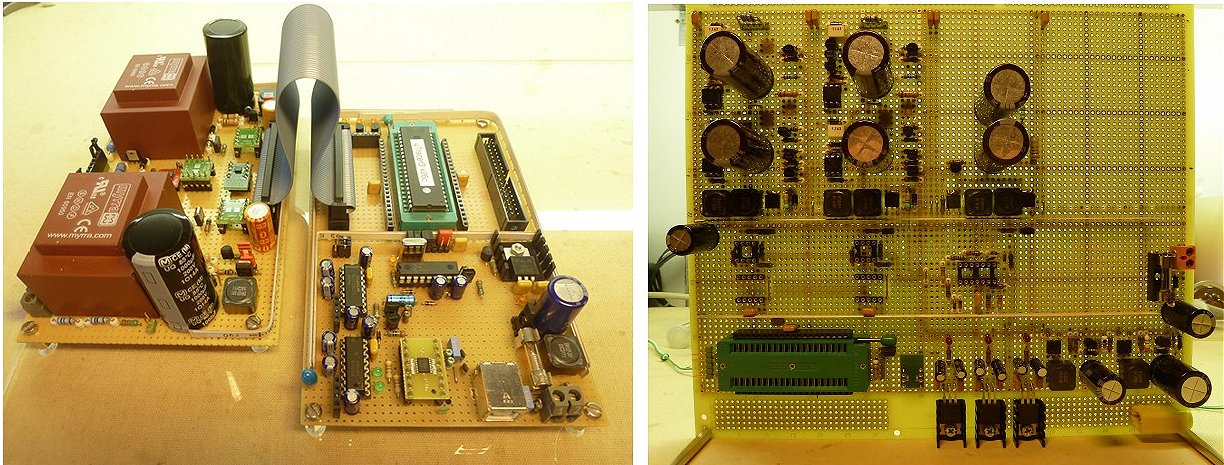
The perfboard prototypes of the uTracer4 (left) and uTracer5 (right).
This more or less triggered the
uTracer5 project.
The main problem for voltages between 500 and 1000 V was that at that time it was very difficult to get affordable electrolytic capacitors and transistors that could work at these voltages. The solution pursued in the uTracer5 was to charge two capacitors in parallel to max. 500 V and then, with a trick, switch them in series to obtain voltages up to 1000 V. While executing the project, I made the classic mistake of making things too complicated. To come to “the ultimate tubetester” I started adding so much options and features that it was growing into a monster that would never make it into a kit. I think it is a pitfall that many professionals and amateurs tend to step in! It is sometimes very difficult to balance the tradeoffs between: performance, complexity and costs. It is not easy to stop with a project you have already spend a lot of time and energy on, but it was the best decision. However, the lessons learned resulted in the uTracer6!
The uTracer6
The uTracer6 is the result of the lessons learned from the uTracer5, basically: keep things as simple as possible and don’t try to make too big steps. Additionally it was enabled by the new generation of SiC high-voltage transistors and manageable high-voltage electrolytic capacitors that became available just at that time. Although the uTracer6 contains several significant circuit innovations, the ground plan of the uTracer6 closely follows that of the uTracer3. The big advantage was that that meant that also the GUI for the uTracer6 could be borrowed from the uTracer3 with only minormodifications. This greatly reduced the development effort.
A monster 1700 V SIC transistor with an on-resistance of only 0.7 ohm in combination with two stacked inductors and 500 V capacitors pushed the voltage for the anode and screen supplies to 1000 V. At the same time a completely revised high-voltage switch circuit allowed for currents up to 1 A. The grid bias circuit was also completely revised and based on a separate DAC in combination with a high-voltage OpAmp.
An optional
extension board,
a more modern term might be “a shield”, was designed to also generate positive control grid biases, especially for our HAM radio enthusiasts. At positive grid biases, grid currents start flow that can also be measured up to 100 mA. I made it an optional circuit, because many people won’t need it. As an extra bonus a
small circuit
was published that synchronizes the measurement pulses with the mains frequency to allow for the measurement of AC heater powered directly heated (power) tubes.
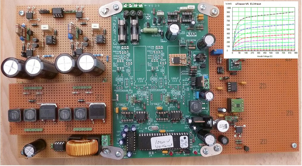
The first prototype of the uTracer6. The insert shows one of the very first measurements, an EL34 (6CA7) pushed to 900 mA at 900 V!
Note also the new strategy, to re-use as much as possible!
The uTracer7 adventure
Although the uTracer6 satisfied the hunger for higher voltages for a large group of users, hard-core HAM radio amateurs kept on asking for even higher voltages, preferably up to 5 kV! So far, the uTracers were based on charging large reservoir capacitors to the desired voltages and use that energy to measure the currents in a fraction second. Inspired by a Marx generator I considered stacking capacitors up to a total voltage of 5 kV, I abandoned the idea because of safety considerations. An electrolytic capacitor charged to 5 kV is a very dangerous thing. Even worse, the capacitor can remain charged even after the circuit is switched off, e.g. in case of a malfunction.
In the uTracer7, the energy is therefore not stored in a capacitor, but in an inductor, more in particular in the inductance of a modified microwave transformer! It developed into a fascinating project. I got a lot of help from my Philips colleague and friend Peter who is a real
transformer specialist! He helped me to understand transformers and he developed an advanced
LTspice model
that allowed me to simulate the circuit. The basic principle of the idea was
convincingly demonstrated.
Work on a prototype was well underway when disaster struck. Unfortunately, my wife was taken seriously ill, which consumed all our attention for the better part of a year. Understandably, this took the pace out of the development of the uTracer7. When after the better part of a year she was doing a bit better again, we were faced with another problem …
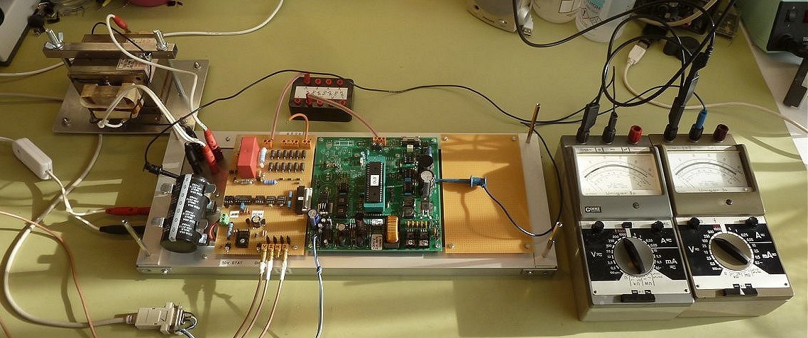
Prototype of the uTracer7.
Note the modified Microwave Oven Transformer (MOT) on the top left.
The idea was again to re-use as much as possible from the uTracer6.
The uTracerNXT
By 2025, the design of the uTracer3 was almost 15 years old. It had proven itself as a stable and balanced design. However, certain components like the high voltage pnp transistors, the OPA277 OpAmp, the TO220 SPA07N60 high-voltage transistor and a number of other components were slowly becoming obsolete and increasingly difficult (and expensive) to source.
My wife and I were left with three choices. Slowly bring the uTracer adventure to an end and fully enjoy retirement, make some minimal modifications to stretch the lifetime of the current design, or completely revise the current design for more modern components and at the same time implement circuit improvements. We choose the last option, and stopped the sale of the uTracer3+ September 2025 and started working on the development of its follow-up.
Obviously during the 15 years the uTracer3+ had been built by over 2300 people, certain aspects of the circuit came to light could do with improvement and updating. The negative power supply was an inherent weak point of the design. The MOSFET based high-voltage switch designed for the uTracer6 proved more robust than the bipolar pnp switch used in the uTracer3+. The accuracy of the control grid bias, especially at low voltages could do with improvement, while there were many requests to increase the grid bias range to at least 100 V.
With these ideas in mind the development of what was initially code named uTracer3.2 started end 2024, more or less coinciding with the illness of my wife, which significantly delayed the project. As usual the development was chronicled in an on-line weblog which provided immediate feedback from readers. The design incorporated the following features and innovations:
- Increase anode and screen voltages to 500 V
- Implement high-voltage switch design from uTracer6
- Increase anode and screen current range to 1 A
- reference cathode to ground rather than to the supply voltage
- Extend grid bias range to -120 V based on external 12-bit DAC and accurate voltage reference
- Use modern single 5 V supply OpAmps eliminating need for +/- 15 V power supplies
- Directly implement the possibility for users to personalize voltage and current ranges
- Add the possibility to use AC heater supplies for directly heated tubes
- Make the board size, drilling holes and electrical connections so that it can serve as a drop-in replacement for the uTracer3+
A new feature is that from the beginning I have taken into account that people can personalize voltage and current ranges to tailor their uTracer to their specific needs, a concept I coined “My-uTracerNXT.” There is an extensive on-line “cookbook” available that will guide people through the process of personalizing their uTracerNXT. The PCB has space reserved for additional resistors and jumpers and Ihor Small has come up with a fantastic idea to make these jumpers easily accessible.
I completely underestimated the amount of work involved in building prototypes, testing, adapting the GUI, writing a completely new construction manual and debugging the design with a few selected beta-testers. But finally by the end of April 2025 we were ready to ship the first kits. My wife never liked the name uTracer3.2. She found the naming of the whole uTracer sequence boring, a bit how cows, kings and popes are named. It started me thinking, and the first “more catchy” name I came up with was NXTracer. However, when I announced the name in one of the newsletters, somebody remarked that it is very foolish to change our brand-name now that over 15 years it had become familiar to thousands of people. I realized he was right so I changed it to uTracerNXT.
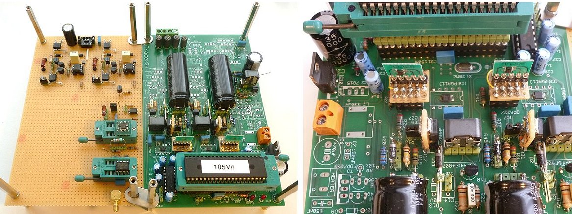
Prototype of the uTracerNXT.
What’s next?
I think that its customary to conclude an historical overview with an outlook of “what’s coming up next”? Well, I am not sure … I am using the extraordinary hot summer days of 2026 to update these pages and we only introduced the uTracerNXT three months ago. So far, the enthusiasm for the uTracerNXT has completely overwhelmed us. At a certain moment we had more than 200 people on the uTracerNXT waiting list! The uTracer “business” has grown from a hobby and we do this mainly as a service from one (vintage) electronics enthusiast to another. To keep things manageable and make it possible for my wife to handle finances and shipment in a personal way, we produce the uTracers in series of 25 kits at a time. We do not have the capabilities nor the wish to scale up production as we value the personal contacts with our customers. So, the coming months we will be very busy making kits and contacting people on the waiting list.
When things settle down a bit, I really would like to pick up the uTracer7 project again. Although also this project had the tendency “to grow a bit out of proportions” I really want to see if a uTracer based on magnetic energy storage is realistic. But, there are also a ton of other, non-tube related, projects waiting. So we will have to see …
A summary of the different uTracer versions
| uTracer1 |
This version never made it further than some exploratory experiments. The experiments are recorded in this Weblog (sections 1-7) |
| uTracer2 |
This version was completed into a working prototype. It used the grid of the tube to switch the anode current on and off and it used a rather curious construction with capacitors to measure the currents. It didn’t perform the way I wanted and the project was abandoned. The experiments are recorded in this Weblog (starting from section 8) |
| uTracer3 |
The first commercial (300 V) version of the uTracer. The uTracer website is devoted to this version. The experiments and development work leading to the uTracer3 are recorded in this Weblog The Graphical User Interface software controlling the uTracer3 is GUI 3 (all subversions) |
|
uTracer3+ Obsolete |
This version is almost identical to the uTracer3 but has an extended high voltage range of 400 V. This version replaced the uTracer3 in December 2014. A uTracer3 can easily be converted into a uTracer3+. Instructions for this conversion can be found Here. There is a small conversion kit available with the necessary components. The experiments and development work leading to the uTracer3+ are recorded in this Weblog (sections 31 and 32) The uTracer3+ requires GUI version 3.11 or higher (see below)! Over the years, it became more and more difficult to source components for the uTracer3+, so in October 2026 we stopped selling the uTracer3. It has now been succeeded by the uTracerNXT (see below). |
| uTracer4 |
The idea of this version was to use transformers to generate measurement voltages in excess of 1 kV. The whole idea turned out to be more complex than originally planned so the project was abandoned. The experiments for the uTracer4 are recorded in this Weblog. |
| uTracer5 |
The idea for the uTracer5 was to create the ultimate tube curve tracer with and anode and screen range of 0 to 900V at 1 A current, negative and positive grid biases and a programmable true DC heater supply. In the end the project just became too complex and I abandoned it. However, much of the ideas found their way into the uTracer6! The experiments for the uTracer5 are recorded in this Weblog. |
|
uTracer6 available now! |
The uTracer6 was the first real new version of the uTracer that was introduced mid 2021! The uTracer6 is a good compromise between performance and complexity. It offers 1000V / 1A anode and screen capability combined by a 0 to -100 V grid supply. At a later stage an extension board with a 0 to +100 V grid supply will become available (including grid current measurement). For a comparison between the uTracer3+ and the uTracer6 see the entry below.
The experiments for the uTracer6 are recorded in this Weblog. |
|
uTracer7 Ideas, thoughts and experiments |
With the 1000 V / 1 A uTracer6 now available as kit, there is still a demand for a uTracer that can go to even higher voltages, especially by Ham radio enthusiasts. I have no idea is such a device is practically and economically feasible, but it is a challenge to think about possible concepts that can enable the 5000 V/ 1A range (pulsed of course).
The ideas, thoughts, and experiments for the uTracer7 are recorded in this Weblog. |
|
uTracerNXT available now! |
The uTracerNXT is positioned as the successor of the uTracer3+. It uses more modern, readily available components and implements circuits learnings gathered over the past ten years with the uTracer3+ and the uTracer6. It offers anode/screen voltages up to 500V @ 350 mA, with a grid voltage down to -120 V. The uTracerNXT can easily be “personalized” for higher currents (up to 1 A), lower voltages (e.g. for battery tubes), or improved resolution using the “My-uTracerNXT” concept.
The ideas, thoughts, and experiments for the uTracerNXT are recorded in this Weblog. |
| previous page | next page |