Most tube curve tracers published on the web consist of a set of programmable voltage sources - say two 0 to 400 V sources for the anode and screen grid, and a 0 to -50 V source for the control grid – which are connected via some matrix switch board to the tube to be tested. After the proper voltages have been applied to the electrodes, the anode and screen currents are measured and plotted, and the next bias point is set. The problem with this method is that since the actual current measurements only takes a very small amount of time, an awful amount of energy is wasted both by dissipation in the tube itself, as well as in the power supplies.
The basic idea behind the uTracer is that in order to measure the anode and screen currents, it really isn’t necessary to have the tube switched on all the time. With this I obviously don’t mean the heater, that one must be on at least a minute or so to stabilize. What I refer to are the high voltages; they only need to be applied to the tube a fraction of a second before the currents are measurement, and they can be switched off immediately afterwards!
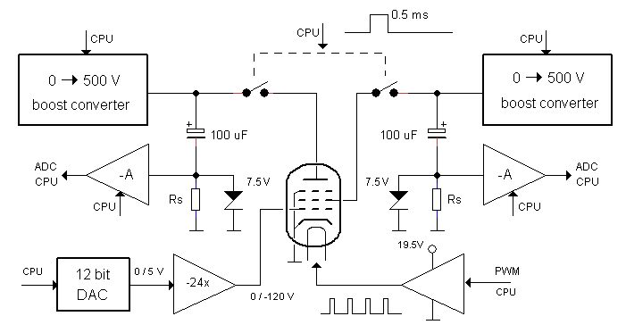
Overview of the circuit diagram of the uTracer tube tester / curve-tracer.
During such a pulsed measurement, the high-voltage power supplies only have to deliver power (P) for a very short time, so that the total amount of energy (P*t) remains small. This simple notion greatly simplifies the design of the power supplies. Remember how the circuit of an electronic camera flash-light works? A tiny circuit charges a large reservoir capacitor until a voltage of a few hundred volts is reached. During the flash, the reservoir capacitor delivers in a fraction of a second hundreds of Watts to the Xenon flash-tube; but since the time is so short, the total amount of energy is still quite low so that the circuit can even be powered from a battery. The power supplies in the uTracer basically work the same way. A tiny boost converter, in reality nothing more than an inductor, a transistor and a diode, charge a large electrolytic reservoir capacitor to the required voltage. Then, only during a fraction of a millisecond, the charged capacitor is connected to the tube via an electronic switch. During this short interval the currents are measured. Immediately after the measurement, the capacitor is again disconnected from the tube. During the measurement the reservoir capacitors are discharged to some extent. This is measured, and taken into account for. After the measurement cycle, the boost converters charge the capacitors to the next bias point so that they are ready for the next measurement.
The whole process is controlled by a fast micro-controller, which performs all the necessary tasks simultaneously. First of all it takes care of the charging (and sometimes also discharging) of the reservoir capacitors. Secondly, it controls the pulsed measurement itself: programs the current amplifiers, measures the currents and communicates the results to the Graphical User Interface (GUI) on the PC. Next to that there are a few other tasks running on the back-ground such as: controlling the inverting boost-converter for the negative power supply, and controlling the heater and control-grid voltages. The uTracers have a “hard-wired” over-current protection which limits the maximum current. Next to that there is an interrupt driven programmable over- current protection which switches off the high-voltage supplies in case a full short circuit situation occurs. Through the efficient combination of hard- and software it was possible to reduce the hardware for the uTracers to the absolute minimum.
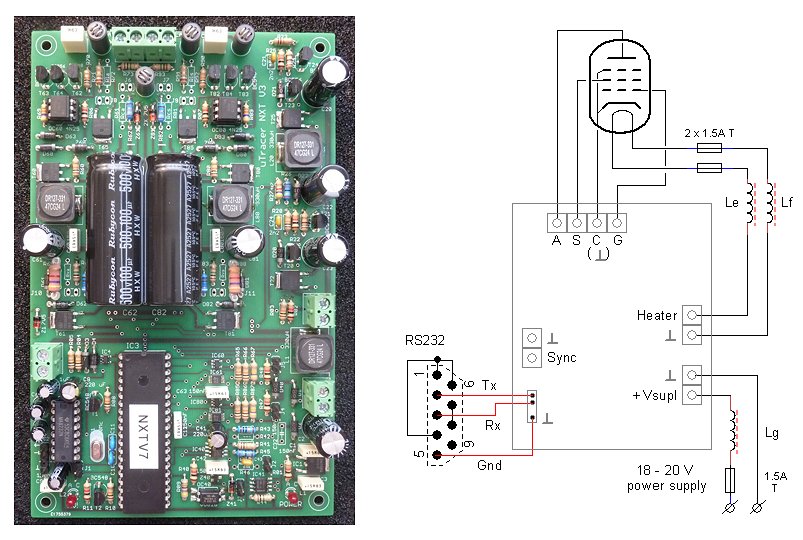
The basic (minimal) uTracer configuration requires an (old) 19.5 V laptop power supply, a tubes socket and a RS232 connection to a laptop or desktop.
The uTracers require an 18-20 V power supply, capable of supplying at least 1.5 A current. An old 19.5 V laptop power supply is perfectly suitable for this. Most people will have an old laptop power supply lying around and otherwise it shouldn’t be too difficult to find one second hand on fly markets etc., and of course you can buy a new one or purchase an alternative suitable power supply.
The internal heater supply of the uTracers is very basic. Since the heater of a tube is basically a resistive load, a simple Pulse Width Modulation circuit is used to adjust to supply power to the heater. Admittingly, this is a rather crude way of powering a heater. The heater supply has been a point of much discussion. Many people have requested a more accurate and elaborate heater supply with current sensing etc. The truth is that small commercially available (Chinese) power supplies are so cheap and so good that it is impossible to compete with them. Many people therefore prefer to use one of these cheap (Chinese) power supplies. Also have a look here or look at the solutions people came up with on one of the testimonial pages.
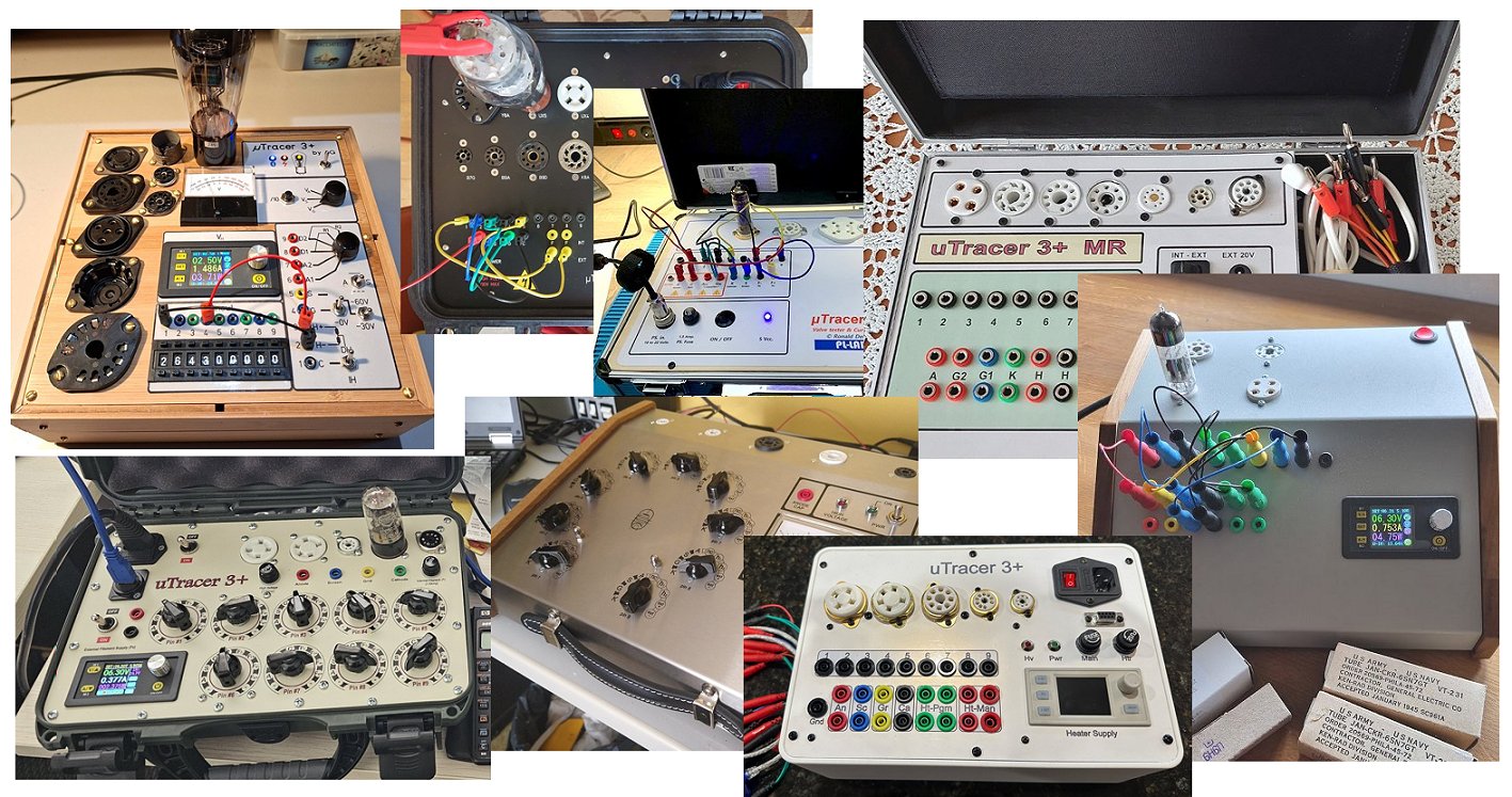
Finally the part where users can use their creativity, fantasy and imagination to create a tube tester specifically to their needs: the connections of the tubes to the uTracer! If you go to the testimonial pages under the tab Testimonials you will find hundreds of creations by proud uTracer owners, ranging from very basic ones with only one or two tubes sockets hardwired to directly test the tubes of their amplifier, to very elaborate systems using rotary switches or even relays matrices to connect the uTracer to a wide variety of tubes.
In the next section the complete circuit diagram of the uTracer tube tester / tube curve-tracer is discussed in greater detail.
| previous page | next page |
Just a small selection of the hundreds of uTracer embodiments that can be found on the testimonial pages.