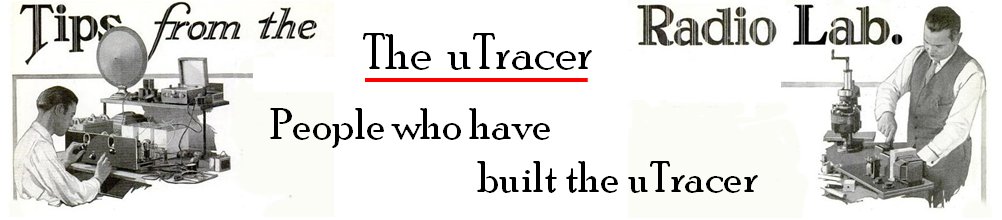
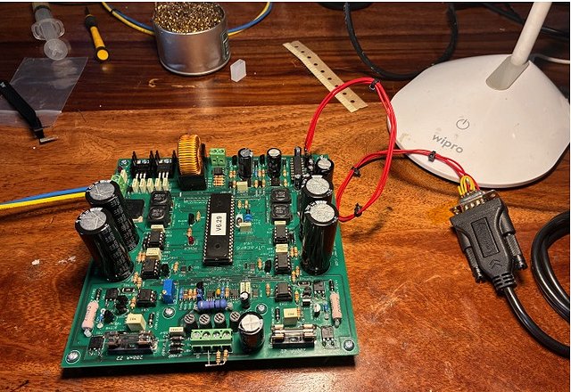
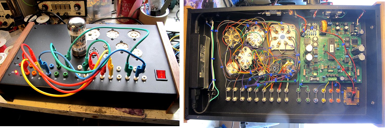
uTracers6 in service:
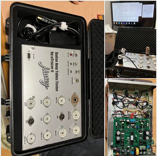
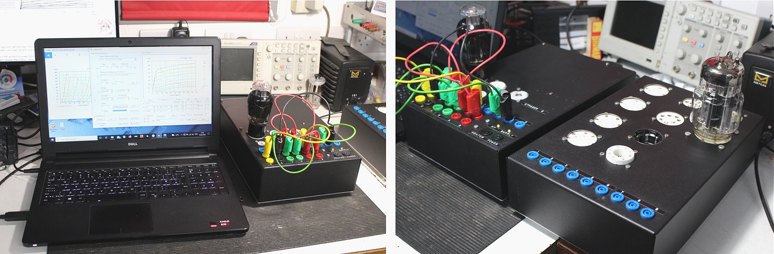
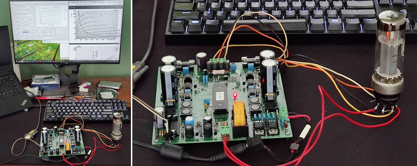
13th of June 2026 Thomas is using the uTracer6 as a starting platform to construct a tube tracer/tester according to his own ideas!
Hello Ronald,
The kit with the extension board arrived safely here in Jena 14 days ago. Thank you very much! As always, everything was perfectly packed and labelled. The assembly instructions are, of course, perfect once again – there aren’t enough thumbs to give you all the praise you deserve. 👍 👍 👍 👍
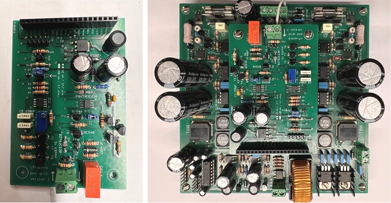
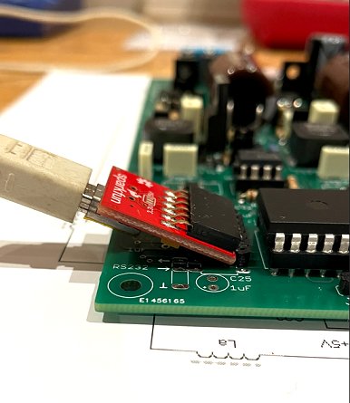
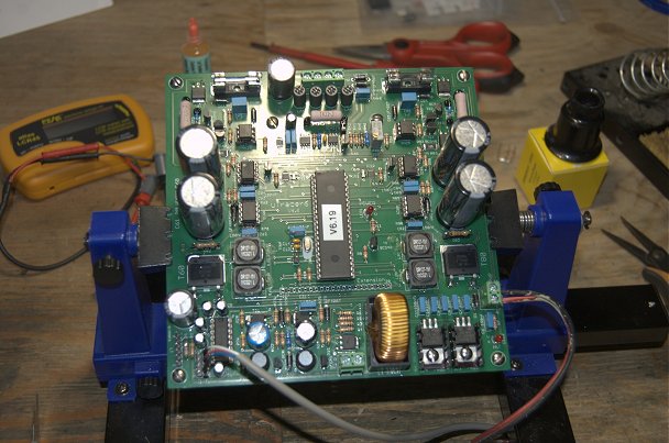
Yesterday I populated the board and mounted it onto the uTracer board. Everything seems to be working.
Now I just need to remove the flux residue and calibrate the board.
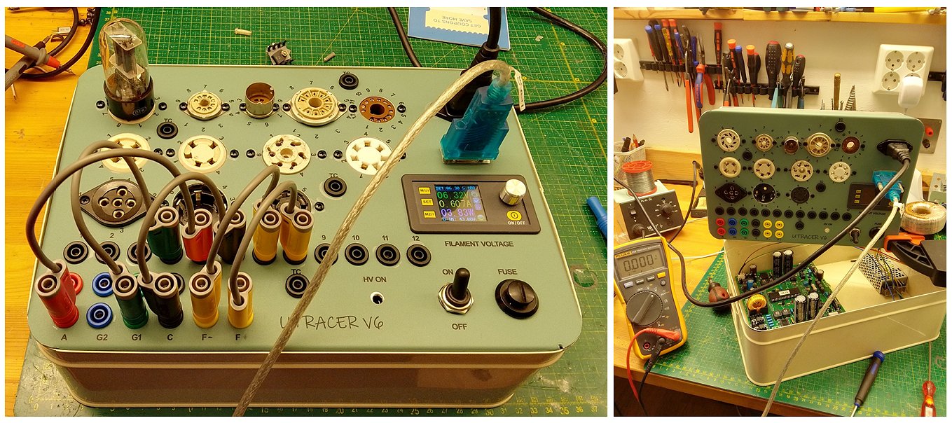
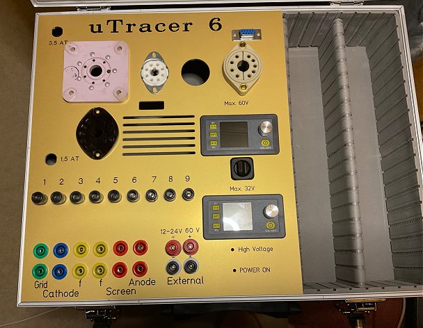
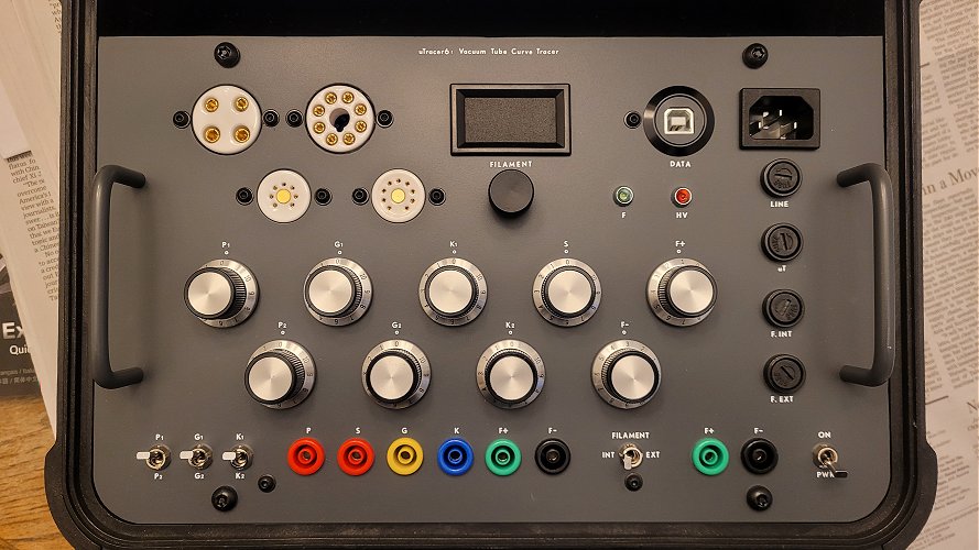
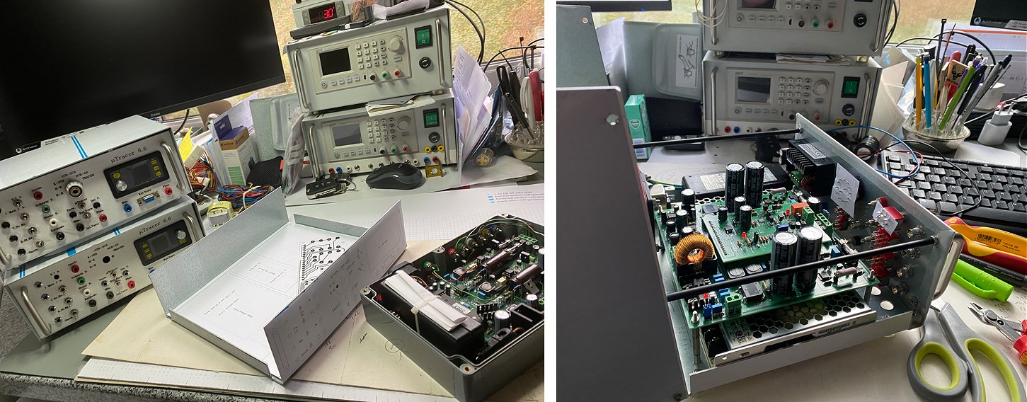
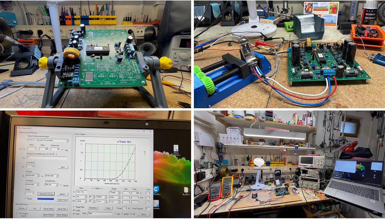
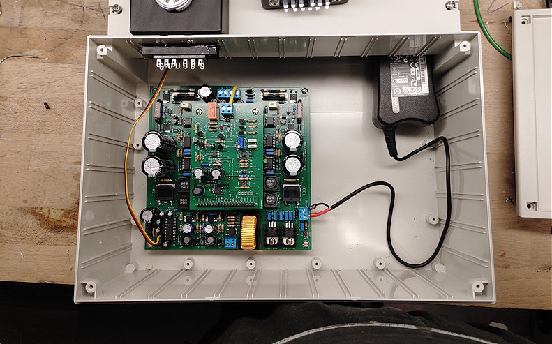
Work on the uTracer’s housing has also progressed. The holes for the various tube sockets have been drilled. Now I just need to drill the holes for the crossbar distributor and the remaining control and monitoring elements.
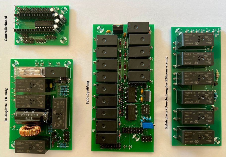
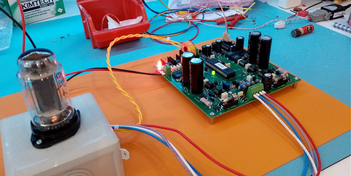
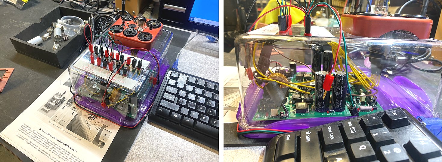
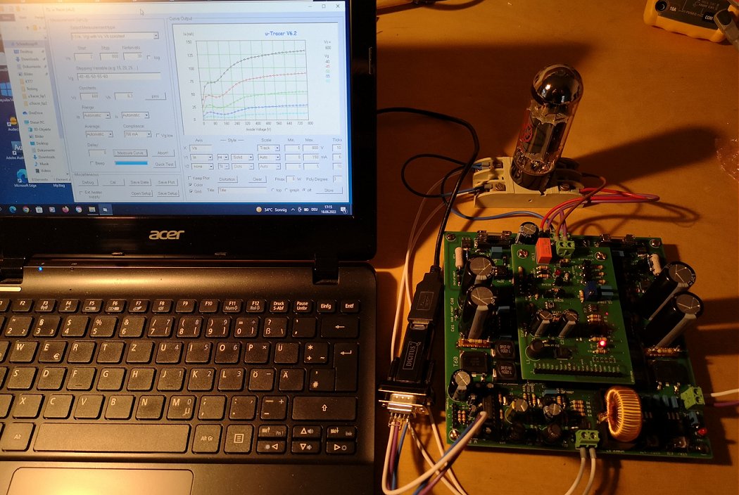
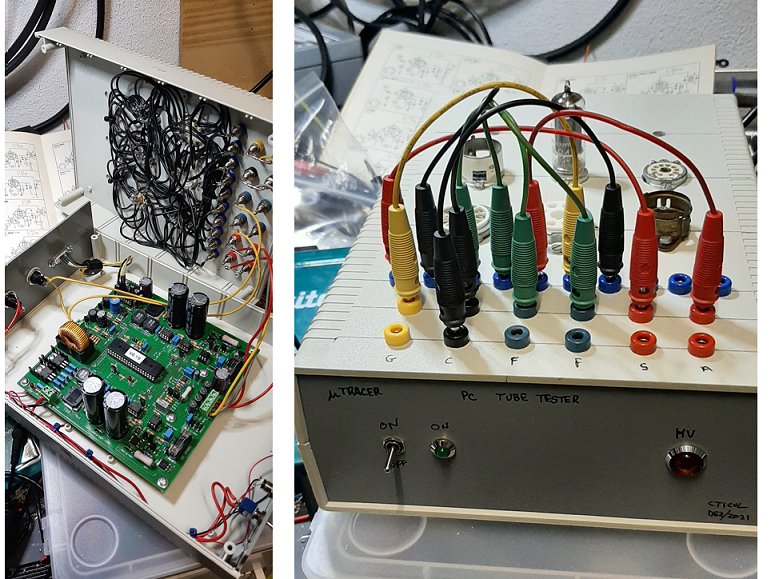
I have also designed a few additional circuit boards that add further functions to the Tracer. A board with 3 relays enables the testing of multi-tube sets by connecting the individual systems to the uTracer’s terminals one after the other. I have already had this board manufactured and am in the process of populating it.
Another board enables testing for short circuits between electrodes. A third board allows the various heating modes (from the uTracer, controlled by the uTracer via an external DC supply, or floating with AC or DC for testing directly heated tubes) to be switched on. These additional boards are controlled by a small Arduino Nano. I have written the firmware for this in such a way that commands for the uTracer are simply relayed from the uTracer GUI, i.e. a single serial connection is sufficient to connect the device to the PC.
I still need to have the boards for the short-circuit test and the heating modes manufactured – I will place the order tomorrow. If you’re interested, I’d be happy to send you the documentation for the extensions.
Over the next few days, I’ll be spending my time setting up the Audion with the Russian pencil tubes for SAQ reception. The circuit boards for this arrived the day before yesterday.
Wishing you and your family a lovely weekend.
Best regards from the workshop
Thomas
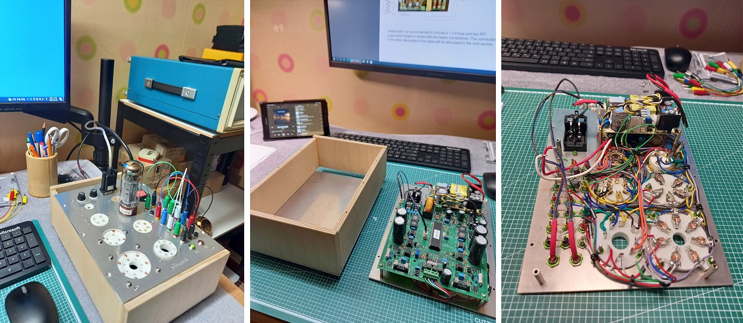
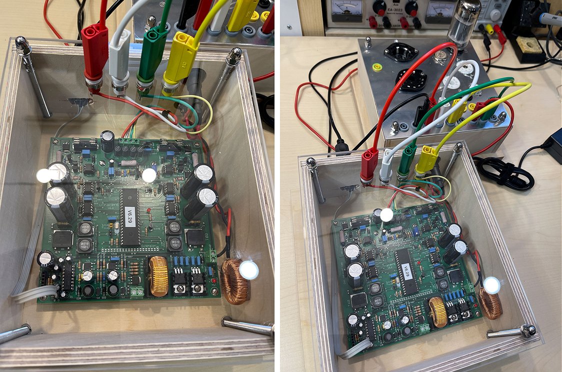
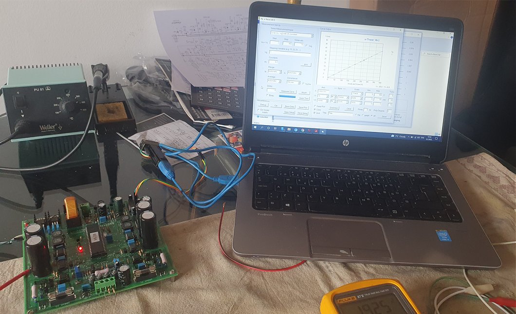
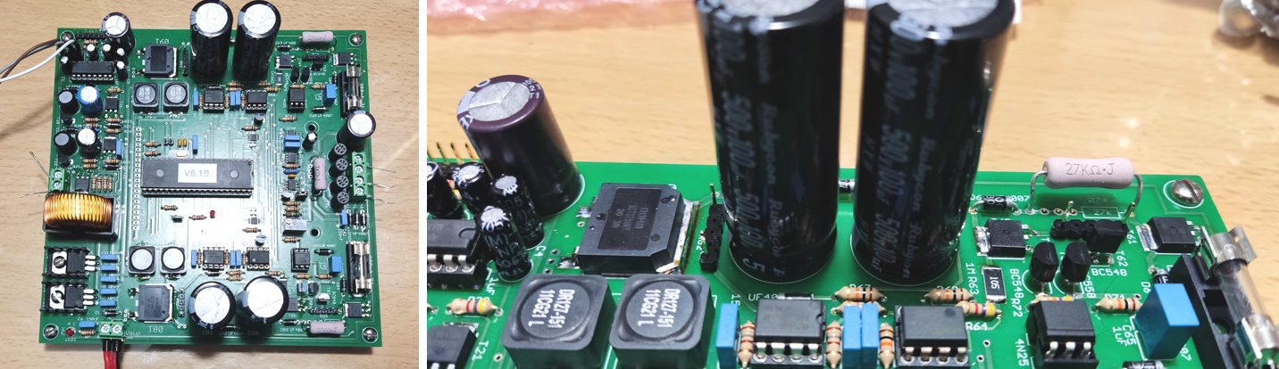
17th July 2026 Thomas sent me an update, and he is making good progress on his uTracer!
Last week, JLCPCB also delivered the PCBs for my uTracer add-ons, and yesterday the last of the components arrived in the letterbox.
So I’ve been able to assemble all the circuit boards.
Now the PCBs need to be fitted into the casing and wired up. I’ve almost finished the firmware for the Arduino controller (Arduino Nano), which is plugged onto the controller board;
I’ve almost finished it.
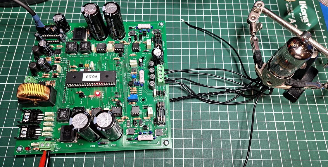
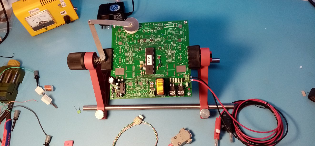
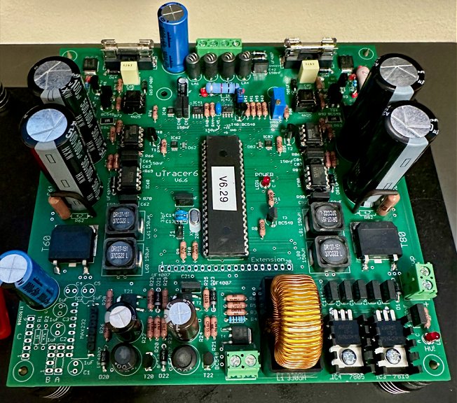
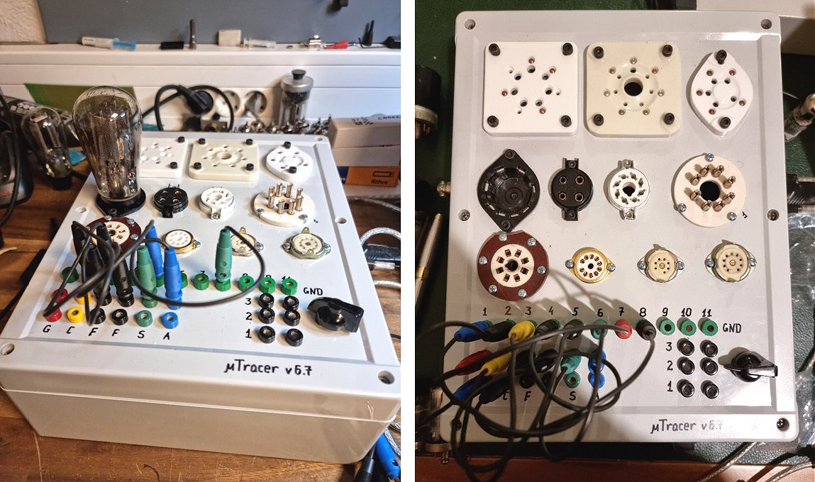
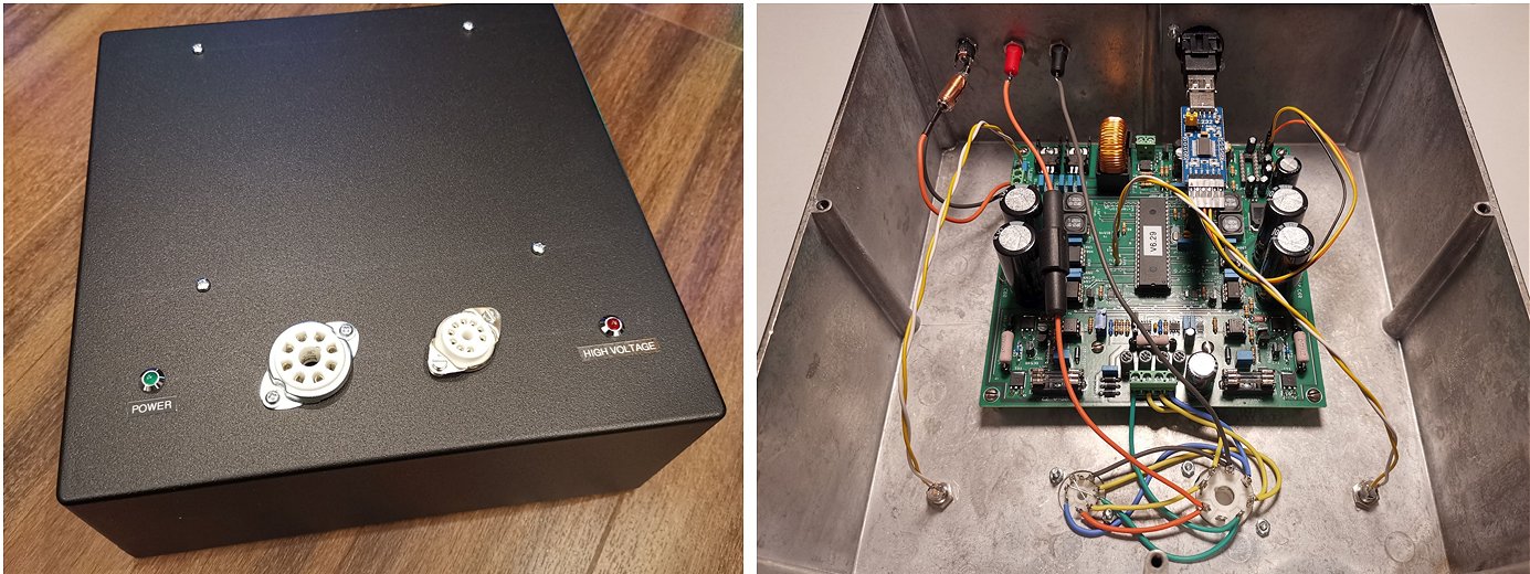
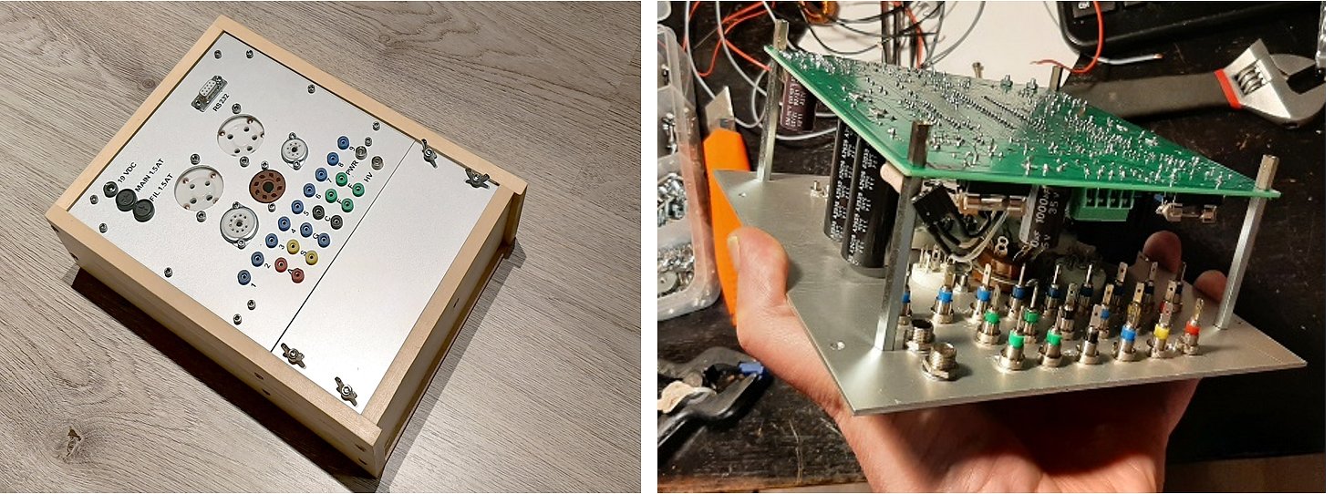
I’ve attached some photos of the PCBs.
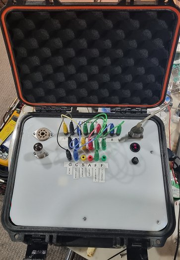
9th of February 2026 Gerhard finished his beautiful uTracer6 and sent me an enthusiastic report!
Dear Ronald,
I would like to sincerely thank you once again for the outstanding uTracer kit.
The concept, the circuit design, the PCB quality, and the documentation are all exceptionally well thought out. Building the uTracer was not just assembling a kit, but a very instructive and enjoyable technical project.
I am especially grateful for your help during the troubleshooting phase. Your advice regarding the two incorrectly oriented capacitors solved the problem immediately. After correcting them, the oscillator started right away and the remainder of the build progressed smoothly and without any further difficulties.
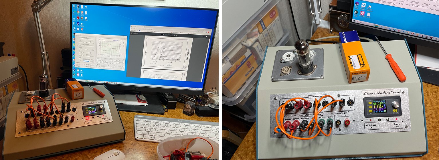
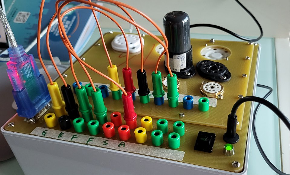
The uTracer is now fully completed and calibrated, and I am very pleased with the final result. I have already started doing measurements and preparing tube data cards for different tube types, which works extremely well with the uTracer concept.
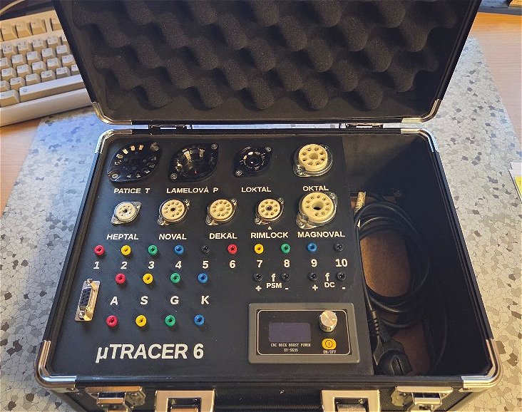
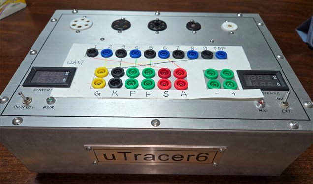
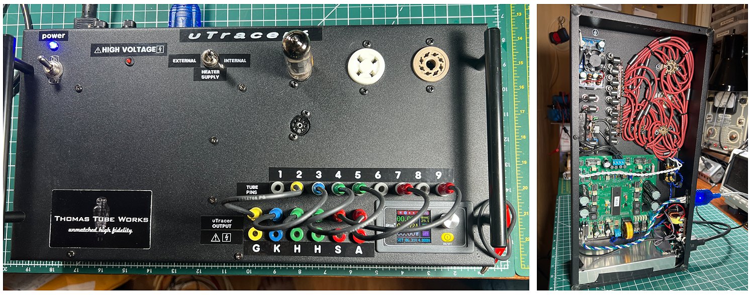
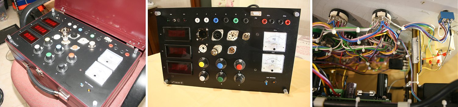
I will send you a few photos of the finished unit, including the socket panel and example tube cards. They show how nicely the uTracer can be integrated into a practical and flexible measurement setup.
Thank you again for your excellent support, your patience, and for creating such a high-quality and educational project. It was truly a pleasure to build and use.
With kind regards,
Gerhard
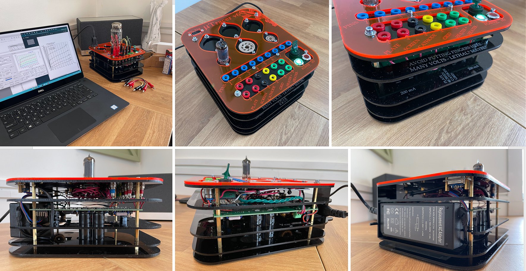
29th of Januari 2026 Alexander from Vienna sent me a few pictures of his splendid uTracer6 and an enthusiastic testimonial!
Hi Ronald,
I just wanted to report back and let you know that I finished building the uTracer6 a couple of days ago. So you now officially have an additional up-and-running reference installation in Austria :-)
It was a great experience to build the kit. Apart from the small hiccup with the two capacitors I initially inserted the wrong way around (where we were already in contact), everything went very smoothly. The whole build process was really enjoyable, and it definitely helped me further improve my soldering skills. Testing and calibration also worked perfectly fine right from the start.
While the electronics themselves were very straightforward and trouble-free, the bigger challenge for me was the housing. I took inspiration from one of the projects you posted on your website and decided to design and build a complete enclosure made from acrylic. The first prototype ended up in the trash, but the second one turned out really nicely, and some of the design decisions I made proved to be spot on.
As you can see in the photos, the final result is quite compact: about 20 × 20 × 10 cm. I managed to include five tube sockets, and I have absolutely no issues with oscillations. That may also be due to the fact that I was very generous with ferrite beads—every connection to the tube sockets has one. They’re not a big cost factor, and I thought “better safe than sorry.”
Now that my uTracer6 is finished, I can honestly say I absolutely love it. It works like a charm and will guide me on my journey into the world of tubes. I’m still quite a newbie in that area, but with this setup, I feel well prepared and ready to explore this new and exciting field.
Thanks again for all the effort you put into making such a great kit.
Best regards from Vienna
Alexander
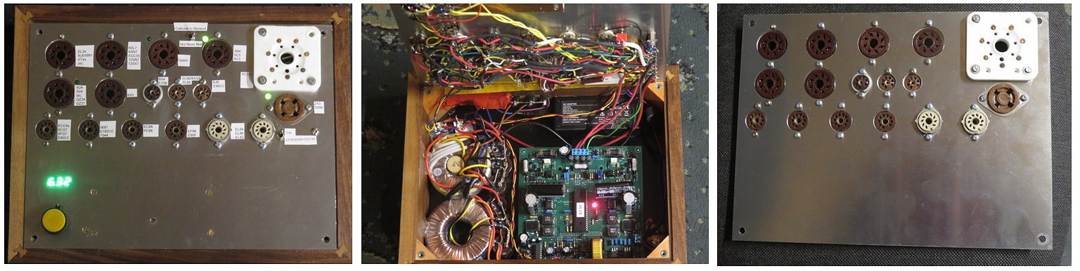
26th of December 2025 John sent me a few pictures of his uTracer in progress!
In an earlier mail he wrote me:
Marie-José and Ronald,
I just completed the build of the uTracer6 and wanted to send a note for two purposes. First, I wanted to wish you both a very Merry Christmas, Happy New Year, and good health for 2026. Secondly, I can't thank you enough for your work on this product. I have built countless kits in my time and this one, by far, was the most rewarding. Your board is top class. The packaging of components is perfect, and the construction manual is as good as I have seen. I was actually kind of sad when the build was complete as I was enjoying it so much. Now, I am looking forward to many hours of experimentation with the uTracer.
Regards,
John
In a second email he added:
Feel free to post my feedback on your website. Yes, the case is a work in progress as seen in the photos. I still need to paint it, do some labeling, add a couple of digital panel meters, and finish the lid. I elected to go with the simple banana jumper approach to individual socket modules. While this isn't as clean as so many other builds I've seen, it simplifies my life, which is important to me. The removable lid will latch to the bottom similar to the TV-7 tube tester design. There is storage for the socket modules, power supply leads and a tube reference handbook in the bottom. I am using external bench power supplies for both the uTracer and heaters. The banana jumpers will be stored in the lid. She won't win any beauty contests but it will be highly functional. Still quite a bit of work to do on the case. Am having so much fun using the uTracer that it will be difficult to put it aside so I can finish the case :)
Regards, John
6th of December 2025 Zappa sent me a few pictures of his beautiful uTracer!
Hello!
Here's some pics of my new u tracer 6!
Thanks again for your work.
Best regards and merry Christmas!
Zappa Francesco
15th of November 2025 Harkirat from India reported his uTracer working!
Dear Ronald & Marie-Jose,
Hope you both are in good health.
Wanted to give a quick update.
I managed to get the board assembled and working. Was absolute fun doing that. Brushed up on my soldering skills :)
I am thoroughly impressed with how you have gone about making it a fun DIY project along with the functionality.
Would have loved to have leaned from you the approach and thoughts when designing. If ever you fell like sharing your experience I would love to listen to it.
From feedback perspective I have limited. The construction was uneventful. But I did want to share something.
In the manual - on Page 39, installation of R77 & R97 is a bit tricky. Its not very obvious form the image. I think mentioning the PIN numbers for the DIP socket where the resistors are connected may be helpful.
In the software - it’s a bit tricky and not very intuitive. Feel a bit of a UI change or documentation may be required.
I have not yet decided on how I want to do the enclosure. So there is some journey left.
Again thank you for making it fun.
Regards,
Harkirat
16th of October 2025 Angelo reported his uTracer working!
Dear Ronald,
I’m happy to announce that my medical condition is improving and that I found energy to finish the assembly of the uTracer 6!
Thanks to the good instruction manual it was an easy task to populate the PCB and to do all the testing and calibration work. I did minor modifications. Instead of using 0,56R and 4,7R Resistors for the current sensing, I’m using 1R and 6,8R. That’s sufficient for what I plan to do. I also replaced the HV LED for a super bright one. As I have no case for the PCB at the moment, I felt it to be a fair safety modification.
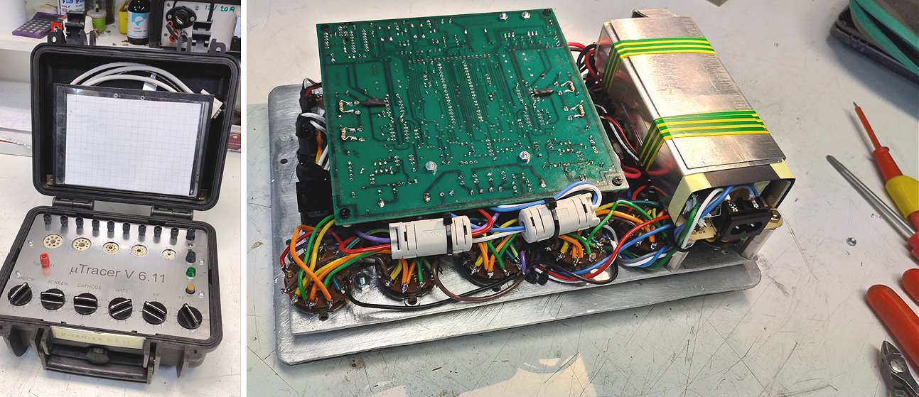
Over the time, I had different ideas considering the case. My first idea was a 19“ rack with cartridges. As the dimensions of the uTracer 6 are not compatible with euro cartridges, I dismissed the idea. I have a few tube testers, and after thinking I came to the conclusion to keep things practical and reuse things I already have. I own a MX-949/U and a Weida W18N Type 2 extension box. I’m planing on getting a similar case like the W18N tube tester manufactured. This way I can clip the Type 2 extension box to my uTracer and have it nicely stored. Until I get the case manufactured, I’m using junction boxes for the tube sockets. It’s a clean and fast to modify solution at the moment.
I’m very happy with the uTracer 6, thank you for this great tool!
Best regards,
Angelo
9th of October 2025 Jiri sent me a picture of his magnificent uTracer along with some useful tips!
Hello Marie-Jose and Ronald,
just to inform you, that your set uTracer 6 kit and extension board is finally completed and work better than expected. Picture attached demonstrate the outer design and construction of the whole uTracer.
Maybe the 330uH coil recommended for connecting the power can be add to the kit as well. In my case I used just 33uH and it is working fine.
If you will plan in future to update the main board, holders for fuses on power supply intake as well as on heating with RFI suppression coils will be beneficial to be integrated directly on the board as well.
Documentation for HW construction is very good and simple to follow.
Regards
Jiri
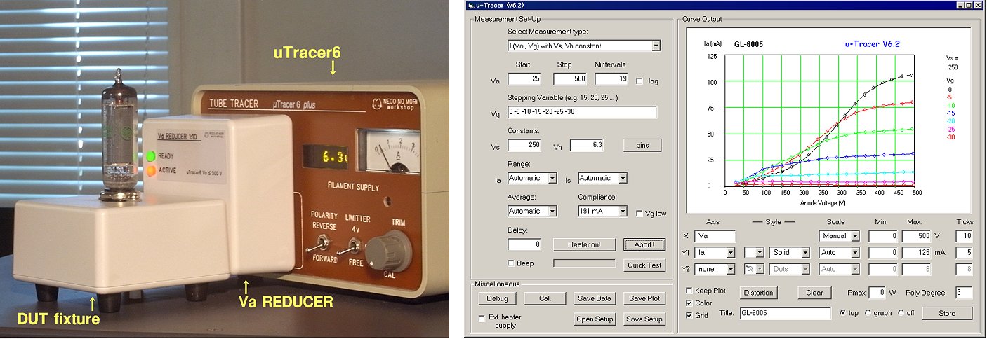
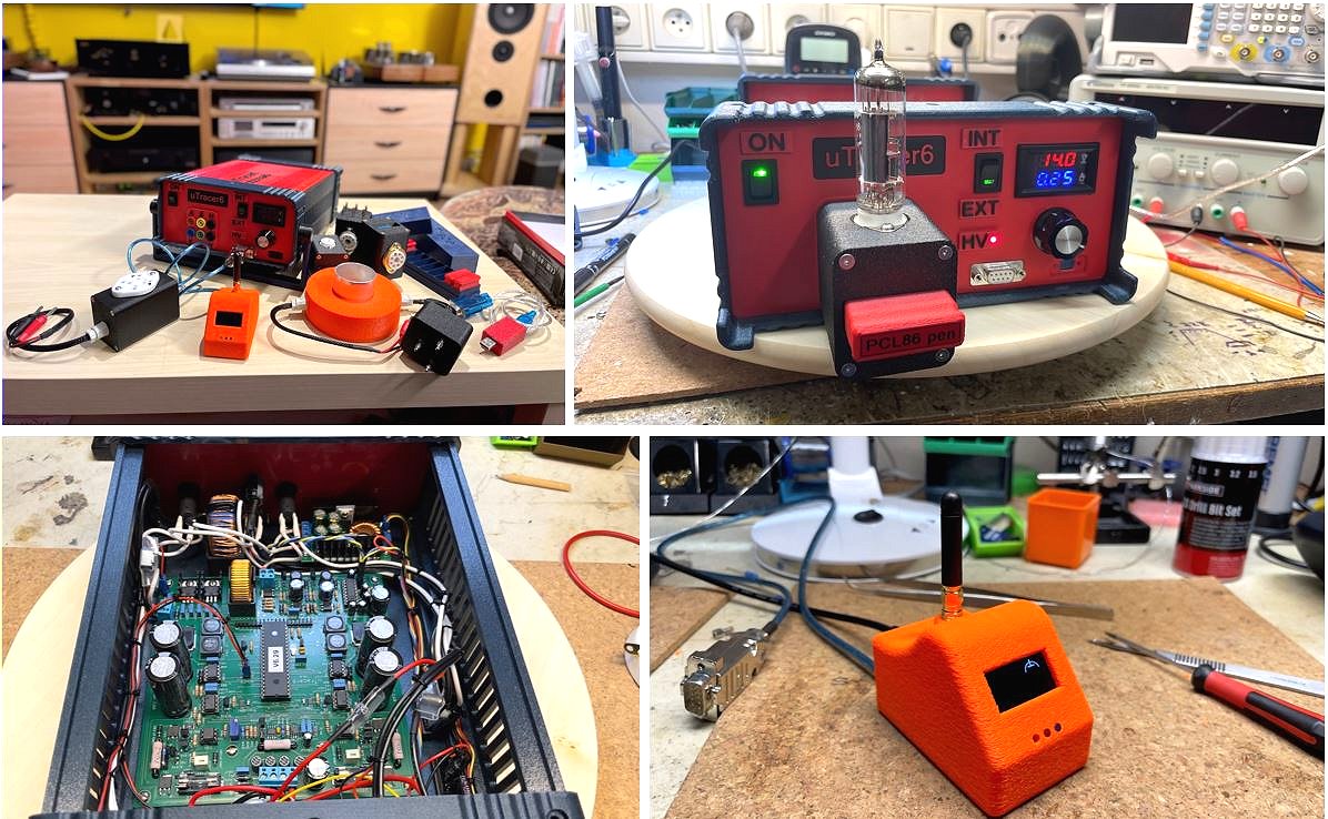
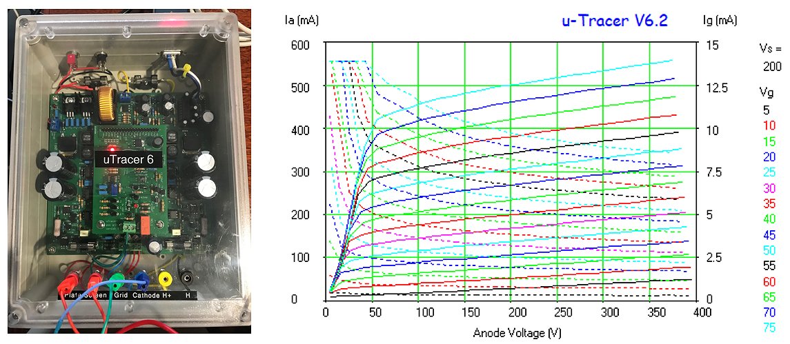
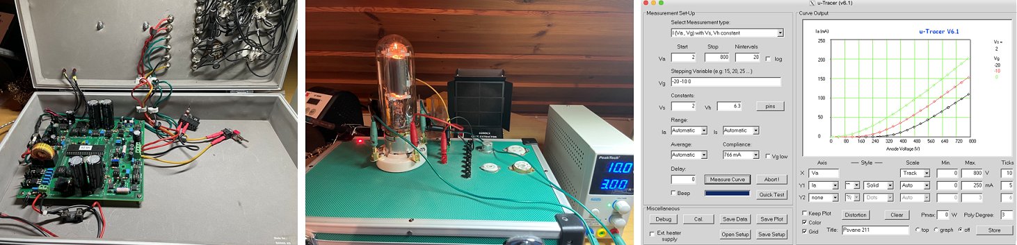
5th of October 2025 Shinichi from Japan sent me a picture of his beautiful uTracer with Va reducer! (read below)
Dear Ronald & Marie-José
I was really surprised to hear that you were seriously ill. And now, I'm glad that you both are feeling better.
My uTracer6 operates very well.
I can't imagine designing vacuum tube circuits without it.
I made an accessory to extend the measurement range of the uTracer6 to the low-voltage side.
It applies one-tenth of the uTracer6's anode voltage to the DUT.
This allows for fine tracing of the region below 50V anode voltage.
I named it 'Va Reducer'.
tracing.png : My Tracer6 is tracing a GL6005 with 'Va Reducer'.
gui.png : Trace result. Please read the x-axis as 50V full scale.
'Va Reducer' requires no modification of either uTracer6 or GUI.
Due to the ASO limitation of the MOSFET being used, the measurement range is limited to below 50V or 500mA.
But 'Va Reducer' is convenient when considering rectifier tubes or A2 operation.
For now, a quick update.
I will also send detailed information, such as the circuit diagrams, later.
It will get colder from now on.
Please take care of yourselves.
Sincerely
One of the authentic uTracer lovers, Shinichi
Of course, when Shinichi shares the schematics and details, I will be happy to share it with all of you!
30th of September 2025 Wilbert sent me a picture of his beautiful compact uTracer!
Hoi Ronald hier een paar fotootjes van de bouw van de uTracer, aardig wat werk geweest maar de moeite waard. Het werkt prima!
30th of September 2025 Jeff sent me a picture of his uTracer6 from Taiwan!
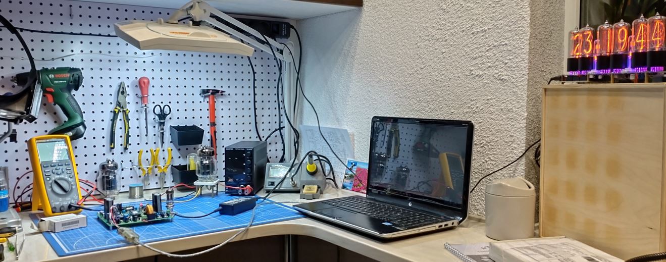
30th of September 2025 Have a look at Louis’ uTracers and his workshop!!
Bedankt voor je Bericht Ronald!
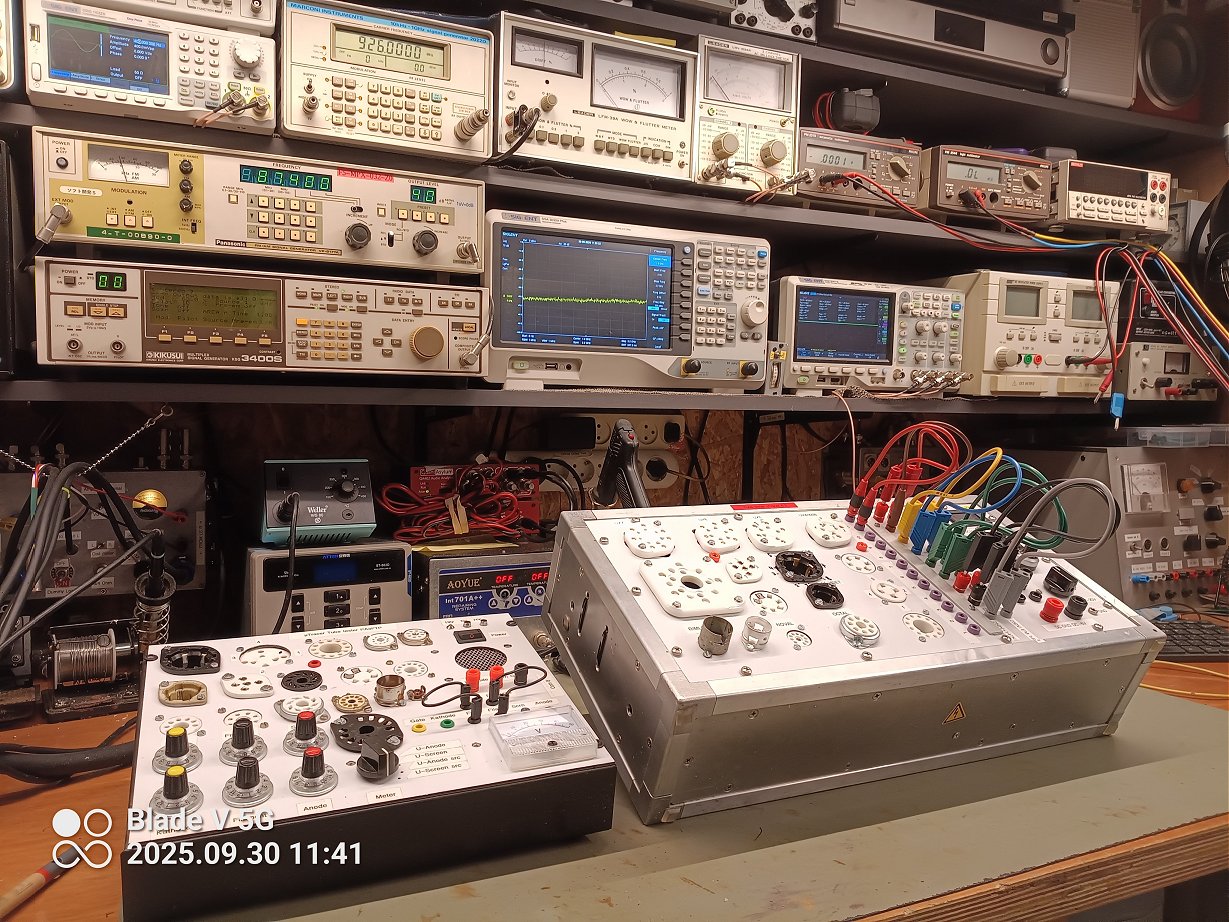
Ik gebruik de uTracer 6.2 regelmatig in mijn experimenteer werkplaats. Op bijgaande foto de 3 en de 6 gebroederlijk naast elkaar
Keep up the good work ?? zou ik zeggen. Als de 7 uitkomt ben ik uiteraard van de partij!
73!
Louis
7th of August 2025 Thomas finished his great uTracer!
Dear Ronald -
I hope you and Marie-José are well and you're enjoying a nice Summer season! I feel it's more appropriate to contact you directly and not via Marie-José since I've got a few technical questions.
First of all, thanks so much for the troublefree interaction regarding the purchase of the µTracer 6 kit! I've got to report that I finished assembly with a few modifications, especially regarding the Serial interface (I'm using an isolated USB/UART coverter). It seems some builders of your kits are having trouble using some sorts of USB/UART bridges, but IMO, most are related to ground-loop related interference. A true galvanic isolation will eliminate any and all of these problems. FYI, that's the isolator that I used: https://www.ebay.de/itm/403341286087?var=673386894573. Don't worry about the 3.3V label, the isolator chip (3Peak TPT7721) is suited for 5V as well and performs flawlessly.
Since my intention was to have the whole unit as compact as possible and not to use tube sockets installed in/on the enclosure, I looked around for an attractive, full metal casing that's just big enough to install the µTracer PCB without much hassle. Once again, our friends from China came to the rescue... https://www.ebay.de/itm/264598523970. Admitted, that's not really cheap, but it just fits the project too well, and it's going to be the component one is dealing with most of the time when using the instrument, so the spending still makes sense...
You may now want to have a look at the (...sorry, way too many...) attached photos of my setup before I refer to the modifications and the add-on board and the related questions / suggestions.
As you may have noticed, I left the RS232 level shifter / driver section completely unpopulated since I anyway was going to use the USB converter mentioned above.
Instead of the UF4007 diodes, I used DV6P for D60, D65, D80 and D85, since if the anode / screen voltage is pushed up to 1kV, the UF4007 is for my own part too much at the limit spec-wise. I tested them to break down considerably higher than that (usually in the 1200~1400V range), so they should actually be okay, but since I had the 6kV diodes left over from another project anyway, it was an easy replacement...
I added a clamping Schottky diode in parallel to the heater output terminals so any induced voltage spikes caused by parasitic (or deliberately installed oscillation-damping) inductances will be kept from the power switch T4. I'm aware that (very) high in-line inductances may result in too high filament power, but without the diode, the resulting high-voltage spike would lead to overheating of T4 and eventually its destruction.
In-line with the negative filament connection to the front of the instrument, I installed an 1.5A polyswitch fuse (the red heat-shrunk blob next to the filament internal/external supply selector switch). If this will actually save T4 in case of a dead short on the filament circuit, is something I didn't dare to test yet... ;) .
And now for the interesting part: As per your suggestion, I set up a small PCB with a comparator for measurement synchronization in case of an external AC-supplied, directly heated cathode tube. I used an LM311 comparator since I didn't need multiple comparators in one package like the LM393, and the 311 has got the additional advantage of providing a ground connection for the output, thus allowing a direct interface to the PIC input terminal. The PCB houses a pass-through for the power LED and a reed relay to select the two positive grid supply current measurement ranges without having to have the signal routed through long(ish) wires to switches at the front. Once again, this probably wouldn't have been necessary, but since I've still got a full stock of these relays from an ancient project, I simply used one...
And here's what surprised me: If the comparator output is kept low continuously (by offset or an externally applied DC filament supply), and a tube measurement is performed, the µTracer firmware locks up and requires a hard (power cycle) reset. The µTracer GUI (v6.2) then notifies the user by two messages (screenshots "Error1" and "Error2" are attached).
I assume that the synchronization via RC1 of the microcontroller is probably a software-polled routine since Port C isn't capable of "interrupt-on-change" and the CCP2 unit is certainly in use elsewhere, so a "capture" interrupt couldn't be "misused". But wouldn't it be possible to implement a "pin change recognition" via a software XOR against a flag instead of a level-sensitive recognition, so a constant DC logic level (either Hi or Low regardless) wouldn't affect the normal operation of the µTracer?
The reason for my question is that I would like to have the µTracer as versatile as possible, allowing to supply the filament externally by DC of either polarity and by AC as well. Currently, a positive filament supply vs. the cathode potential results in the Microcontroller to lock up with the measurement synchronizer circuitry attached. And that's unfortunately the configuration that all the tiny battery tubes are expected to be operated in.
Obviously, I could remove my add-on PCB when working with external DC filament supply. But since the problem can be solved with a firmware revision which may also benefit others, it may be interesting to look into it anyway. I've still got a few surplus add-on PCBs, so if you would like one for experimenting, I'ld be happy to provide it to you.
Please feel free to use any of the attached photos or information contained in my (way too long...) message on your web site.
Thanks again and all the best,
Thomas
29th of June 2025 Another uTracer6 has come to life! In Romania this time!
Hi Ronald,
I hope this e-mail find you well!
I'm pleased to report that another uTracer 6 is born (attached a picture with an ECC83 tube in testing). I have no idea how many there are in Romania but for sure there are not too many.
Anyhow, I want to congratulate you again for the fine piece of kit you prepared. The documentation is reach in details and based on it, everything went smoothly.
All works right from the beginning.
I'm still very excited having such a tool on my hands and I will spend some time testing tubes. That is for sure :)
Next, I will continue with the positive grid add-on but right now I'm so busy with the uTracer itself that I have no easy for anything else :)
Again, please accept my congratulation for the good work you've done with the kit.
Keep up the good work and keep in touch for the future development.
Wish you a good health and interesting experiences.
Kind regards,
Cristian
ps. from Ronald: There are at the moment in Romania 5 uTracer3 and 1 uTracer6 in operation.
21st of May 2025 Angelo is making good progress with his uTracer6!
Good evening Marie-Jose and Ronald,
it’s sad to read that you are struggling with health issues. I’m happy, to read that both of you are recovering.
It’s horrific what some people are willing to do, to earn a few bucks with cheap copies. The price for the original µTracer is fine, it comes with high quality components and you put a lot of effort in it. We have a saying, perhaps it might cheer you up: “Nur die guten Sachen werden kopiert.“ = „Only the good stuff will be copied.“
My goal was to have my µTracer ready 2024. Well it’s 2025 now and I just started assembling it. The controller is responding :-). Next Chapter is the negative power supply construction.
Your construction manual is amazing!
I put a photo of the current state to this mail.
I hope I soon can find some time to proceed assembly.
Best wishes!
Angelo
7th of April 2025 Adam from finished his very fine uTracer6!

Hello Ronald,
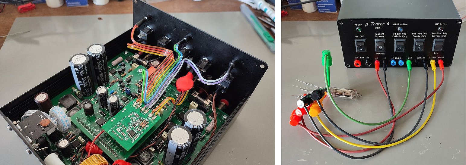
It took more time than I expected, due to other cases I had to cover, but finally another uTracer6 is (almost) finished! :) See attached pics of unit itself and the first measurement of ECC82. Yeah! >p> As you see I add the external heater supply with additional switch to easy select between internal and external one. It is XY-SK60 module from aliexpress powered from the same laptop power supply as the tracer itself. This module additionally shows the heater current and offers overcurrent protection which can be helpful sometimes. For connection to computer I used TTL-232R-5V cable, it works completely flawlessly. I used standard Hammond mfg. aluminum panel enclosure. Switch descriptions are 3D printed but I have to print it again - I forgot to add the pin numbers :) Except that it needs only some small mechanical tweaks for finish.
Summarizing, it was really nice experience to build it. It is very likely that I will use it frequently for checking tubes for my customers and to match them myself for push-pull amps. Only one thing which could be, let's say better, is the PCB. Personally, I would like to have a bigger pads. I'm not too young and sometimes it was hard to see if I soldered it correctly ;)
Thank you very much for uTracer!
Best regards,
Adam
24th of March 2025 Markus reported his uTracer6 working!

Hi Marie-Jose,
The yTracer6 is completed and fully works. With the detailed step by step instruction nearly everybody can build one.
In the manual v6.11 page 41: there is a typo in the first line. T77 should be named in R77.
One critical point:
it is mandatory to use a stable Com Port Emulator (FTDI) or if you have an older computer: use the native Com port.
Ch340 and CP2401 are not the best choise.
Attached you will find a few pics of the finished kit with a GU50 transmitting tube attached to it. You can use the pics on your webpage.
I wish you a good time
Markus
Ronald:
The Ch340 and CP2401 are USB<->serial converters with TTL(5V) or even 3V output.
For the uTracer you need to use a real USB<->RS232 converter with the +/- 10V voltage pulses, adhering to the RS232 standard.
See also: FAQ_H4
2nd of March 2025 Ray cased up his uTracer6 and pictured it next to its older uTracer3 brother (or sister?)

Hi Ronald,
Here are the rest of the promised pics after I completed the uTracer6. Working perfectly! Note the one next to its uTracer3 little brother...
Thank you for great kits.
Ray
10th of February 2025 John reports his uTracer6 working!

Hello Marie-José and Ronald,
Pleased to report another uTracer 6 up and running in Poland. Absolutely no problems whatsoever, as I expected. Lovely kit, great construction manual and a super website full of information.
The uTracer software installed on a new Windows 11 64-bit laptop with no issues at all, and there were no problems with the RS232 -> USB adapter, virtually plug and play.
Attached are a couple of photos of the uTracer6 (not in a box yet, but soon) and also a photo of the traces of its first test piece ever, a 12E1 power supply valve, Looks like a good one too :-)
Great stuff.
Thank you very much.
John
9th of February 2025 After a few hick-ups, Ivan reported his uTracer6 working as expected!

Hello Marie-José,
I am informing you that I have successfully completed building and calibrating of uTracer6.
Now to some mechanical work (sockets box preparation, etc.)
I must confess I made one double mistake during assembly in part 10.
Namely, instead of 2 x 4k7 resistors.
I somehow put 2 x 47k in place od R64/R84.
It took me almost 2 hours to figure that out and complete testing of part 10.
Anyway I enjoyed building uTracer6 very much.
Beautifully prepared project and manual !
Best regards,
Ivan
29th of Januari 2025, Wolfgang sent a few pictures of his brilliant utracer6!

Dear Marie-José & Ronald
Finally I managed to find time for this lovely project - and did it!
Everything went smooth as silk thanks to your detailed documentation an perfect material supply!
SW installed on an old WIN7 Laptop - worked straight away.
I measured my lot of ECC83 - picked two nicely shaped ones - put them in my Fender Champ 12 amp - and they sound brilliant :-)
Pls find attached a few pictures of my kit - built in to a 70 years old sewing box from cherry wood.
Each tube type can be wired on a D-Sub 25, double triode with a switch: very handy and fast to work with
or connected by cables to the 4mm plugs.
best regards and keep developing!
Wolfgang
16th of Januari 2025, Raymond reports another uTracer6 in service in the USA

Hello Ronald,
Just finishing up the uTracer6 I purchased a while back. It got put on the back burner due to life in general :) I have the uTracer3+ that I built first, and it has been flawless so far, so the uTracer6 has not been a priority, but I want to test some bigger triodes now so I got back to it.
I have attached a couple pics and will send some more when I have this one complete. You can add another uTracer6 in service for USA!
Both of these kits are VERY NICELY done. I want to thank both you and Marie-José for your efforts.
Regards,
Ray
22nd of October 2024 Mark send me a few pictures of his beautiful transparent uTracer!

Ronald en Marie-José,
After 3+ years, retiring and moving across the US from California to New York, I've finally completed my uTracer6 and its case.
Thanks for an excellent product and manual.
I went with a modular design for the plugs, which also allows me to use the socket for prototyping.
Kind regards,
Mark
30th of August 2024 Rüdiger sent me a few pictures and a write-up about his beautiful uTracer!

Hi Ronald,
I think I owe you a final update on the uTracer project.
It didn't took me long to assemble the actual PCB, thanks to your comprehensive manual and the testing in stages while building. I tested the finished PCB with flying leads on some EL84 and 12AX7 and it worked right from the start. Very nice.
Finding and finishing the cabinet was a lot more work, as usual. And holidays, work and life got in between, so it took until now to get it completely finished.
I opted for the 2mm banana leads as you use, added the sockets I need now with room to add more and for the internal heater. It worked fine during all my tests and right now I don't see the need to add external heating. I'm well aware of the direct heated tubes and the special treatment they need when using the internal heater.
I've attached some pictures of the build and would like to thank you again for a fine project and a very usable tester.
Regards Rüdiger
1st of July 2024 Ryan is very pleased with his uTracer!

Hi Ronald,
Justin wanted to say thanks for making such a great kit, finished putting together, calibrated and tested a 12ax7 and a 7189a. Opted to go a modular route with separate breakouts for each tube socket (see pic). Had one question, do you have any suggestion for testing tubes with a directly heated cathode. I had this 811a kicking around and was gonna looks at circuit if I connect cathode to one side of heater, but figured I’d ask if you had already thought about it. BTW, still on the tube building adventure, setting up turbomolecular pump I. Coming weeks.
Thanks again
-Ryan
27th of May 2024 Tjerk from Amsterdam sent me a picture and measurement of his very compact uTracer6!

27th of April 2024 Stephen finished his very fine uTracer6!

Ronald,
Just an update on my uTracer6. This is now fitted in a Hammond 500-0940 panel enclosure, which also has space for the laptop power supply. I have fitted Hirshmann 2 mm sockets (type 2630) on the sloping top and stackable plugs (type MST S WS) for the jumpers. These are rated at 1000 V. At the moment I have added B9, Octal and 4-pin (DHT triode) valve bases to the flat top surface. I enclose some pictures with a 6BM8/ECL82 on test and jumpers for the pentode section.
Thank you for your help and support during the build.
Stephen
30th of March 2024 Jun finished his very fine uTracer and made a 3D step file for your convenience!

Hi
Marie-José and Ronald
I thought I'd drop you a line to let you know that I've finished assembling the uTracer6. It was quite an enjoyable experience. Additionally, I've created a rough 3D model for my personal use to aid in parts placement when integrating it into the case. It might prove useful for other users too. I'll include the STEP file, so feel free to make use of it.
Best regards,
Jun
For those of you, like me, who have no experience with 3D CAD files, Jun sent me a link to an online step viewer:
https://imagetostl.com/nl/bekijk-stp-online
20th of March 2024 Sergio reported his uTracer6 working!
Hello Marie-Josč
it seems everything ok and working fine, pls see the picture! just the Vneg it is different from the value in the manual, it is still ok?
thank you Sergio
29th of February 2024 Tapio’s uTracer6 and extension board are working!
Greetings from Finland,
I finally had time to complete the uTracer6 extension boar. For my surprise everything worked right away :D I first tested new General electric 6146B with Vg +10, Va to 500V and Vs 200V, Va/Ia curve was exactly as in data sheet. I am now very happy owner of the power full instrument. I am still collecting other parts to boxing the tracer. I have quite reasonable schedule, I think, so If everything is ready in next summer then all has gone well. Update will follow.
Take care and have a nice time
Tapio
27th of Fabruary 2024 Thomas turned a 99 cent Tubberware box into a transparent uTracer case!
Hello Ronald.
I finished putting the utracer in a case (a Tupperware box from the 99 cent store) I added stackable mini banana plugs and I took the tube socket test fixture from my Hikock 3000 tube tester. It has all the beats installed and it just plugs in via a 11 pin tube socket, this way I can use it with the utracer and my Hikock 3000 tester. Thank you for all your work, the tester works great. For a Manley Vari Mu compressor I am repairing, I had to test all kinds of different tubes, including diodes it works!
20th of Fabruary 2024 Tommy (finally ☺) finished his fantastic uTracer6!!
Hello Ronald,
It took me a few years to get it done, but made it a priority this winter and now its ready for service. Kit came together without any issues, perfect! Only suggestion would maybe be a "locking connector" where the rs232 connects to the board.
Found the perfect box at Ikea by coincidence, had my friend cut a front panel after my fusion 360 design, on his cnc plasma cutter. Front panel decal was made by a local company, turned out really nice. Have not decided on whether I'll use the lid.
Have tested a few small signal triodes and beam tetrodes, works well after I found a short hiding in one of the sockets (thin solder splash across two pins).
//Tommy, SA2CLC
10th of Fabruary 2024 Christian made a beautiful case for his uTracer6!!

Dear Ronald and Marie-Jose,
I just finished the case for my uTracer6, and thought you may be interested in how it turned out.
The case is made from poplar plywood with (iron-on) walnut verneer, then stained and varnished. The panel was made on my fathers CNC machine (took around 7 hours, since we only had 1.5mm endmills).
Now I hope I don’t get too much oscillation issues, and I due to all the small sockets I only trust the socked board up to 600-700V so far. Also I seemingly switched up some pins on 2 sockets, still have to fix that.
Regards,
Christian
9th of February 2024 Tapio from Finland reported his uTracer6 working!
Hello Marie-José & Ronald
Finally, I got something to show you. Here is the picture of the first ever test I run with my uTracer. I have some old EL84 tubes and all of them seems to be let say "not in good shape".
Assembling the kit was easy and fun but of course some troubles were on my way. First one unsoldered resistor end in one of the negative power supplies. It was easily fixed. Then no output from anode and screen supplies... I fail to solder one coil end and both big FETs drains. Also easily fixed but it little annoys me because I have 37 years experience from electronics industry R&D and I thought that I know how to solder. :-) Anyway, next to assemble that extencion board and see what happens then. I am also collecting parts for boxing the uTracer. The box I have should be little bigger, let see if I can fit all the stuff in.
Greetings from Finland, and have nice time for waiting the summer. I also wait it because we ha now -19C outside...
Tapio
8th of Fabruary 2024 Thomas’ uTracer is working and he immediately put it to good use!
Hello Ronald,
I finished building your tester, everything worked the first time, even though I still need banana connections I had to use it right away yesterday repairing a LA2A compressor.
Thank you for your great work.
22nd of Januari 2024 Terry from Idaho is very pleased with his uTracer6!
Ronald,
My uTracer6 is doing great stuff. I have been working through my tube collection, comparing data on the uTracer6 with my favorite old tester a TV-7D/U that is calibrated and updated. The uTracer has less variation for sure, and can obviously do things a tube tester can’t do. Comparing the gm measurements and plate currents has been illuminating. The TV-7 correlates very well with the guicktest results. It can really only give me gm and plate current (one of the updates), but I wanted to make sure that if I sell a tube my data will make sense in the context of what people are used to seeing. Can’t really sell a lot of 30 tubes by putting the plate curves for all of them in an ad! But offering them to a buyer is quite valuable. Pic below. The matrix of switches is an experiment that hasn’t gone well…
Can you give any advice or ideas on scripts or code that will analyze a group of curves across several tubes and find patterns in the lot? I have hundreds of files now and I am SLOW at comparing them! Cheers!
Terry
3rd of Januari 2024 Doino from Bulgaria reported his uTracer6 working!
Hello Marie-José and Ronald,
Happy New Year! During the holiday I built the uTracer. Everything went well. The documentation is excellent. It's working like a charm. Some interesting aspects of my build are:
- I upgraded the quality of some components so that the build out lasts me. :D I understand your idea of keeping it affordable, I just enjoy nice electronics. Still waiting for those DRA127 to eliminate the fuzz.
- I immediately went for the USB connection described here. It worked very well.
- I discovered the uTracerJS project, so I set up a Raspberry Pi Zero 2 W. The Raspberry OS has drivers for USB TTL, so it worked out of the box.
I'm still working on the boring parts - wrap it in a box, power supplies, tube sockets, etc. If you would like I can send you some pictures afterward.
Thank you both,
Doino
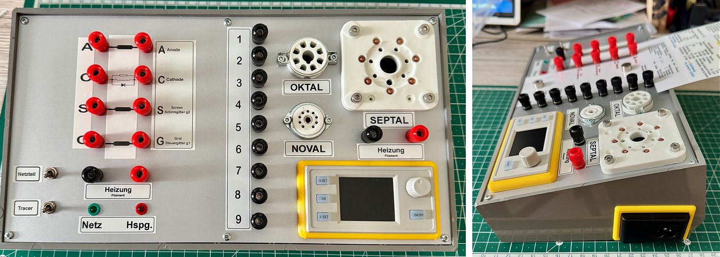
2nd of January 2024 Oskar from Germany was the first to finish his uTracer6 in 2024, and he immediately tested a giant tube from 1928!
Hi Ronald,
First of all: Happy new year and the best wishes for you and your family!
I used my vacation time to go on with „my“ µTracer and I can say, it is in full working condition now. After one day of concentrated assembly work, the unit was completed and calibrated. This was possible, because of your very well prepared kit (description and parts).
This tube is an heirloom and I always used it as a deko object for dekades. But now it is clear: Anode current and transconductance is still according to the datasheet. Not bad for a vacuum tube from around 1928. Remarkable: this tube comes from a time, where getter has not yet been used.
Ronald, my uTracer is in full working condition- I am SO HAPPY – many thanks for your preparatory work!
The uTracer is one main part for my Röhrenkennlinienschreiber. Now the project has to go on with sort of „socket unit“ and „connection distributor“. But I’ll have to sleep on it a few more times.
Ronald, thats it for now.
Thank you so far.
Kind regards and best wishes
Oskar
10th of October 2023 Mark from Canada is very pleased with his uTracer6!

Hi Ronald and Marie-Jose',
I have completed the uTracer 6 Kit with no issues at all.
The instructions and manual were very well put together and all the steps and procedures well explained.
I would like to thank you for the hard work that you have put into this project and the decision to share it with tube nerds all around the world like myself.
I have included a couple , well maybe a few more than a couple, of pictures of the uTracer 6 as built by myself.
I have yet to test some of the bigger transmitting tubes that I have so I've only had the tester up to 700 Volts during the build and testing process.
The picture shows the testing of a 6J5 Philips Triode in progress.
I have much to learn about this unit, the testing it is capable of doing and what it all means when analyzing a working tube.
Once again, thank you so much for offering such an exciting, well designed and well put together, tube tracer ' kit '.
VA7MNV
Mark
3rd of July 2023 Andrew from Thomas Tube Works sent me a few pictures of his magnificent uTracer6!
Hello again,
I thought I'd share with you and Ronald how I have made out with my uTracer, I completed and calibrated it and then tested a tube on the bench and had great results. I then planned and designed my enclosure and wiring, I had in stock a Hammond 16x8x3" chassis so I decided to use that. I added an adjustable buck boost converter to run large filament tubes. My goal was to make a simple and neat enclosure design and wiring to keep things simple and organized. I have added the 4 tube sockets I use the most and have adapters for the rest. I tried to keep the wiring neat and organized and followed Ronald’s advice on adding the ferrites. I also add the RLD combination in the cathode. I have had zero sign of oscillations and have been more than pleased with the results of the uTracer! I have over 3000 tubes that I would like to go through and sell what I don't need so it will be put to use without a doubt. The whole experience building it was excellent and I had so much fun! so thank you to the both of you for all your hard work and everything you have done.
20th of April 2023 After a few hiccups, Siegfried is clearly enjoying the construction of his uTracer6!
Hi Ronald,
Here the beginning of the finishing of the tube measuring device.
Thank you very much again Ronald for this wonderful kit, very instructive manual and support.
13th of April 2023 Jim sent me a picture of his magnificent uTracer6! Did I ever mention that I love those rotary selectors?!
Hello Ronald & Marie-José,
I hope this email finds you both happy and well.
I purchased a UTracer6 last year and the project turned out great (I blew up the processor, but you graciously sent me a replacement at no charge). However, a close cousin was very impressed with its functionality and performance, so I decided to give him the completed pc board but kept everything else. Now I have my project half complete again and would like to purchase another uTracer6 kit from you, hoping you still have one left for sale. Attached is a photo of my uTracer, sadly sitting idle. I will definitely send you more pics of my project when completed.
Best regards,
Jim
27th of March 2023 Georgi sent me a few pictures of his uTracer and he is ordering a second one!
Hi Ronald and Marie-José,
I hope you are going well!
Thanks a lot for the uTracert 6 kit, it's been working perfectly for a long time and I'm still going to send you pictures.Please see attached pictures.
I would very much like to buy another kit of uTracer6 kit (1000 V version) and uTracer6 positive grid extension board .
Please inform me about availability and payments.
Thanks in advance.
With Warm Regards
Georgi
7th of March 2023 Mike sent me an update on the progress of his uTracer6!
Hi Ronald and Marie-José,
Just a quick update to let you know that construction and calibration of the board is complete. Your instructions are fantastic - clear and detailed - so many thanks for your diligence with this. My next task is to construct the case and mount everything ready for use. When that's done I'll send you some photos.
In the meantime, here is a photo of the small FTDI break-out board I am using to connect the laptop (https://www.hobbytronics.co.uk/ftdi-basic). It connects using a mini-B USB cable. Using this should allow me to fit a standard type B USB connector on the rear of the case and connect to it inside using a short cut-off mini USB cable. I can then use an off-the-shelf USB cable to hook up the case to my laptop.
Kind regards,
Mike
7th of March 2023 Masatoshi posted his great uTracer6 on Facebook!
Dear Marie-José, Ronald,
I recently completed my utracer6.
In addition to the high voltage and power supply indicators, I have also added a parallel led on the heater as an indicator.
I hope you will find a brief introduction on my Facebook page.
Click here to visit his facebook post.
Thank you for providing a very good product. I look forward to working with you in the future.
Sincerely, Masatoshi
12th of February 2023, Aman from China sent me a few pictures of his fantastic uTracer6!
Dear Marie-José:
I have successfully completed the installation of the equipment, which took a lot of energy from me, but the result is very exciting because it works happily for me.
I would like to share this joy with you, and I hope you can add it to your website to share more people.
Thank you very much.
Thanks again !
Aman
4th of February 2023, Julian from Germany sent me a few pictures of his efficient uTracer6!
Dear Marie-José, Dear Ronald,
I ordered my uTracer6 in March 2022 and finally found the time to complete the build. The whole process went really smoothly, and all the tests after each build chapter passed on the first try. So I wanted to thank you again for the great kit and detailed documentation. I attached you some photos of my uTracer6 build. I used the Hammond 1550NBK housing and I can definitely recommend it. It is already powder coated in black and is a perfect fit for the uTracer.
I am mostly using my uTracer with a laboratory power supply as an external heater supply. When testing big tubes like an EL34 that require 1.5 A heater current I personally find the PWM noise of the integrated heater supply quite annoying. But as you stated on your website, it's hard to compete price-wise with the many ready-made buck converter modules you can find on eBay.
Best regards,
Julian
28th of January 2023, Jorma from Finland finished his beautiful uTracer6 + extension board!
Dear uTracer family, Marie-Jose and Ronald!
Please find few pictures of my uTracer6 with extension board. Construction was easy as the kit and instructions are excellent.
I built my uTracer in a standard Hammond sloped front housing and added a separate front plate for connectors and DC/DC converter which works as an external heater supply. A built-in XP AC- power supply feeds the DC/DC converter.
On top of the housing I added an aluminum plate for sockets. This construction makes socket changes easier if any need arises.
There are still some finishing touches to complete (e.g. socket wiring is still bit messy) but the unit is totally operational in it's current state and has proved to be reliable after six months of use.
The uTracer6 completes my uTracer 3+ that I can trace most tubes from small ones e.g. ECC83 up to big sweep tubes e.g. EL/PL519.
Thank You for this great unit and stay safe!
Kind Regards
Jorma
28th of January 2023, Louis from Belgium shared some pictures on the progress of his uTracer6!
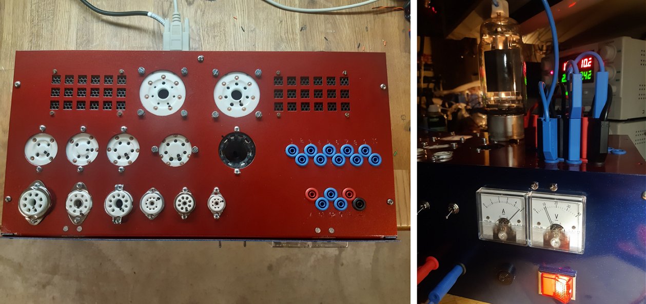
10th of January 2023, Peter finished his uTracer6! (in Dutch)
Hallo Ronald,
Aanbouw is afbouw geworden: eind vorige week was mijn hardware klaar en in het weekend heb ik de print ingebouwd en mijn laptop van de uTracer6 GUI voorzien. En hoera, alles werkt.
Het kostte me nogal wat moeite om de GUI zip te vinden voor de 6 maar ineens stond die toch klaar om gedownload te worden (hoe dat is gebeurd weet ik niet) en daarna ging alles als vanzelf.
Op mijn hardware (zie foto's 1 en 2) heb ik nu de buishouders van etiketjes voorzien zodat duidelijk is wat ik waar kan meten. Ik kies dus niet voor stekkertjes en zo maar voor dedicated buishouders van de regulier voorkomende audiobuizen. De schakelaar bovenin maakt het mogelijk om (op 2 manieren) aan direct verhitte buizen te meten zoals de 2A3/300B/6B4/5U4, over het gloeicircuit hangt permanent 44 ? weerstand met een middenaftakking.
Dat trekt wat extra stroom maar dat is geen probleem want omdat ik de Russische 6C33C (I-ff 3,3A bij 12,6V!) wilde kunnen meten heb ik een aparte gloeivoeding ingebouwd goed voor 5A max, met 50VA 6V en een 60VA 9V trafo’s die door relais worden ‘meegeschakeld’ met de benodigde DC-gloeispanning, dit om oververhitting van de LM338 regelaar te voorkomen. Via die LM338 kan ik zorgen voor 2,5-4-5-6-7-12 Vdc en een displaytje laat zien wat ik aan het doen ben.
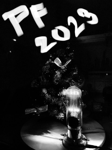
25th of December 2022, Martin from the Czech Republic sent me a beautiful New Years card (below) and so many pictures from his fully 3D printed uTracer6 that I had to make a selection!
Hi Ronald,
I am sending the final chassis solution.
Everything is printed on a 3D printer.
I wish you a nice Christmas.
Martin
16th of October 2022, Martin from the Czech Republic sent me a beautiful step-by-step account of the construction of his uTracer6!
Hello Marie-José,
So done. uTracer6 is completely live and set up. Now I still have to come up with a nice chassis. I am attaching photos from the construction.
Thank you very much for a beautifully and ingeniously crafted kit.
Have a nice day
Martin
15th of October 2022, Jimmy from Indonesia made a nice video of the consttruction of his uTracer6! (Also visit his channel)
10th of October 2022, Frank reports his uTracer6 + extension board working!
Hi Ronald!
Although the Tracer is not finalized yet I'd like to give you a first report.
I completed the boards and had a first testrun on the bench: It seems that everything is ok!
Got an old EL84 hooked on and the results were good. µ is running and the tube is almost new ;-)
While soldering the mainboard I had a near-error-encounter...
In part 10 when the 8 pin sockets are due. I know you marked it with "note orientation" already....
but I'd wish (when I build another µTracer in my next life) to see a hint to the reverse orientation of IC 80&81! It all looks so perfect symetrical...
Right nowI'm fitting it all in a case. I'm going to set up a contact field to connect the Tracer with the tubes. In memoriam Funke/Neuberger with cards for the tube types that make faults almost impossible.
I think about a field of dc-jacks with coaxial 5.5/2.1mm plugs. The plugs will have an internal short between the two contacts.
The jacks will be connected in rows and columns with the Tracer resp. the tube sockets.
For the sockets I steal the idea from Helmut Weigl's RoeTest, with small boxes for each socket.
9th of October 2022, Mr Tsang from Hong Kong reports his uTracer6 working!
Dear Ronal & Marie-José,
My Utrace is working well.
Thank you very much
Best Regards,
Mr. Tsang
12th of September 2022 Rene from Oslo is very pleased with his uTracer6!
Hallo uTracer team ;-),
Vorige week mijn uTracer V6 gebouwd en getest. Eerste buizen getest.
De eerste was een 6SJ7 zie foto pc screen. Heb alleen nog de IO8 buisvoet aangesloten.
Daarna enkele EL en ECH buisjes dmv de MX-949 adapter getest en interne gloeispanning.
Wacht nu op het extentie board voor de definitieve bouw.
Gr. van een tevreden gebruiker uit Oslo,
Rene
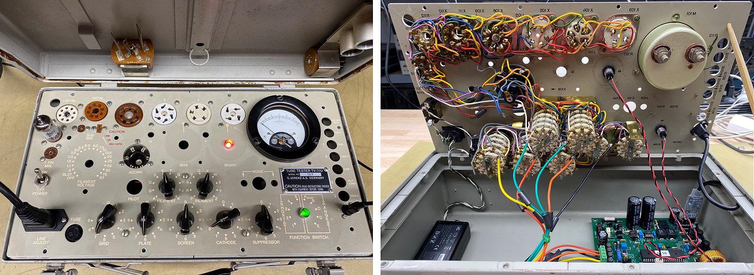
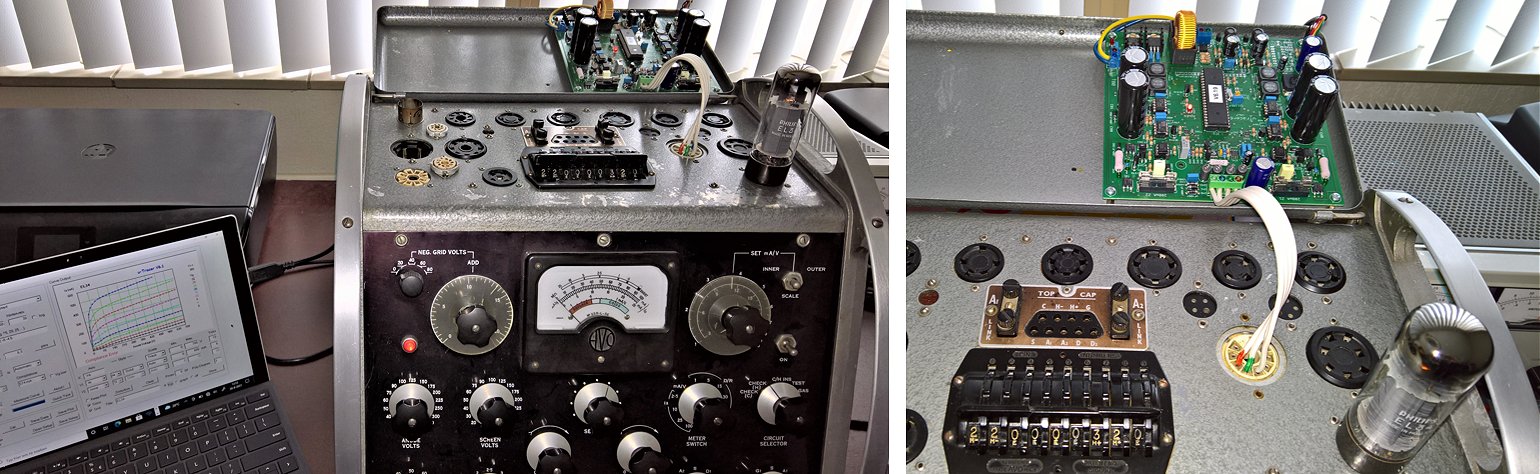
22nd of August 2022 Francois refitted and old TV-7U Tubes Tester with the uTracer6!
Hello Ronald,
The µTracer6 is up and running without any hassle.
As I wanted to save my time, I prefered to refit an old TV-7U Tube Tester with the µTracer6.
I removed everything from the old tester, except indeed the tube sockets and the pin commutations. The nice feature of this model is an elaborate commuting scheme which prevent to short the outputs (K, S, P, G) by mistake. The drawback is you can’t use the circled AVO patented cabling scheme. But, so far, with a few ferrite beads added I did not experienced unstability problems.
The computer link uses a CH340G USB/TTL converter, this one doesn’t need any driver on your computer. Because it’s TTL level, I removed the MAX232, a micro USB socket is available on the faceplate. Next step will be to implement The boffin.nl ESP32 communication module for more flexibility on the Lab. The positive grid extension board will follow, as well as a commutation for external heater power supply.
Thanks again for this nice update over the v3.
Best Regards,
François
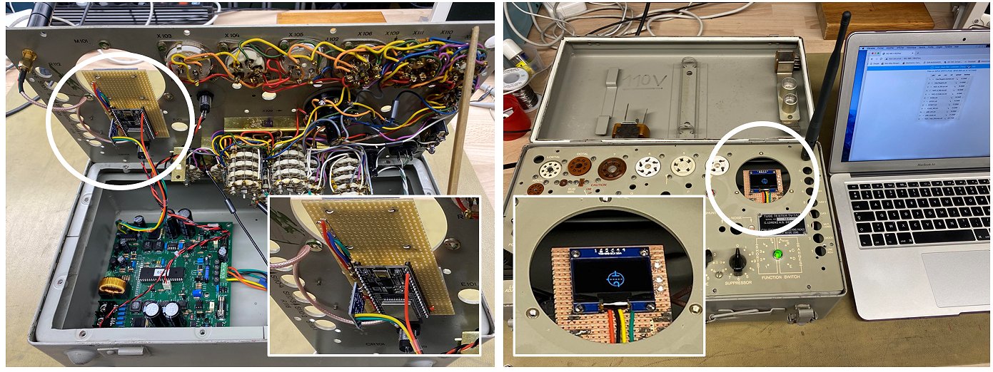
Update! Francois enhanced his uTracer6 with the ESP32 interface from Ihor!
Hi Ronald,
The update with the ESP32 module from Ihor was easy, the little OLED screen and leds took the place of the unused galvanometer of the TV-7/U.
For my daily use, this module adds flexibility in the use of the tracer in my Lab, by providing access via WLAN and standard html browser.
Hereunder a couple of pics of my enhanced µTracer6.
Best Regards,
François
12th of July 2022 Frank sent me a picture of his completed uTracer!
1st of July 2022 Jari sent us a few pictures of his magnificent uTracer6!

23rd of June 2022 Dave from Australia reported his uTracer + extension board working!
Hi Ronald, Very pleased to say that my positive grid extension board is all calibrated and working perfectly. Attached are anode characteristics of a 12AY7 including a +1V Vg trace and a trace of grid current for the same tube at Vg of 0V and 1V.
I don't have any zero bias triodes on hand so I tried my pseudo triode test setup. Attached are 5V to 75V Anode curves for a 6HJ5 Pseudo triode ( screen driven with 1.89k from screen to grid and 10k from grid to cathode).
I have J1 in place and the calibration resistor value set for the 100mA scale so I'm not sure why the grid current curves all peak at around 14mA. It should look like the plot "6HJ5 Pseudo triode uTracer6.bmp" which I made using I(Va, Vs) with Vg, Vh constant (screen standing in for the grid). Still, that has "grid" current going up to nearly 300mA and the extension board will only go to 100mA.
By the look of "6HJ5 Pseudo triode uTracer6.bmp" I might need a screen stopper resistor. If I try this plot with Ihor's software it's wavy too. Looks perfect with my uTracer3 but as you noted the uTracer6 is more susceptible to oscillation.
Pity about the change between 10mA and 100mA grid current ranges requires a jumper change. Bit difficult in my case with the uTracer 6 inside a box. That said, I don't expect to be switching ranges frequently. If I do I can always replace the jumper with a switch.
As with the uTracer3 and UTracer6 kits, this extension board kit was a real tour de force in terms of design, documentation of the development process, construction manual and the kit itself. One thing I really like is the "build a bit, test a bit" approach.
I've built a lot of projects and kits over the years and so many would have benefited from this approach. It's very unusual for projects to work first time for me and when they don't finding the problem can take a lot of time and frustration. The extension board would have worked first time if I hadn't missed the note about 1A slow blow fuses and had fast blow fuses installed.
Thanks again for your amazing work!
20th of June 2022 Peter reports his uTracer6 working!
Hello Marie-Jose and Ronald,
I have finished the uTracer6 and it works great! Attached you will find an image of the finished board.
Followed the manual step by step and the build was easy and fast. Thank you very much for your great work!
Kind Regards
Peter
15th of May 2022 Dario from Venice sent me a few pictures of his excellent uTracer6!
Hi Ronald,
I am sending you some photos of my uTracer6 now completed ....
I also added the circuit to reform the capacitors ....
I hope you like it.
Congratulations, a really nice project. Good job
Dario
4th of May 2022 Daniel sent some pictures of his very nice uTracer6!
Hoi Ronald,
Ik heb de uTracer6 inmiddels afgebouwd. Bijgevoegd twee fototootjes. Ik heb gezocht naar een compacte bouwmethode en hiervoor een soort 'sandwich' gemaakt van het pcb en de frontplaat met een aantal buisvoeten. Een bekabelde foto heb ik niet gemaakt helaas, maar op deze manier is het mogelijk om zo kort mogelijk te bedraden. Het is een beetje passen en meten om de 4 grote elco's niet in de weg te laten zitten, maar uiteindelijk is het goed gelukt. Ook heb ik uiteraard rijkelijk gebruik gemaakt van ferrietkralen. Het kistje is uiteindelijk ongeveer 20x25cm geworden. Frontpaneel een eenvoudig geanodiseerd alu plaatje, en de letters met ouderwetse wrijfletters aangebracht. Het plaatje met de vleugelboutjes is nu nog een blindplaatje (kan er de meetsnoertjes er onderin opslaan), maar kan in de toekomst gebruikt worden als ik andere buisvoeten nodig heb.
Bedankt voor het samenstellen van de mooie kit,
groet,
Daniel
1st of May 2022 Peter from Australia reports his utracer6 working!
Hi Ronald,
Working perfectly.
Next step is a cabinet and valve base fixtures.
I prefer a little sub-cabinet for each base type, which then connects to the uTracer6 via a short cable and octal plug and socket.
Many thanks for such a fine kit, that is almost impossible to build incorrectly with such excellent and detailed instructions.
All the best to you and team.
Kind Regards,
Peter
24rd of April 2022 Shin-ichi has his extension board working and he immediately traced a 4P1L in triode mode!
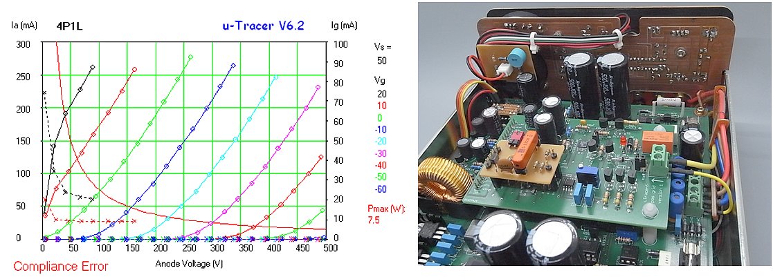
Dear Marie-José and Ronald
Yesterday, I received the stray transistor. Thank you very very much !!
Immediately, I have completed my uTracer6 with the transistor.
My uTracer6 works with the extension board so nice !
Attached image is one of the first traced graph, 4P1L triode connection.
It tells me the real design request. Wonderful !!
The uTracer6 system is the most excellent tube tracer in the world, I believe.
Thank you !!
Shin-ichi
Shin-ichi also made a small circuit that automatically increases the gain of the OpAmp when the smaller current range is selected

This is the description in his own words:
This is a gorgeous looking of uTracer6 system with the extension board.
A small brown board piled on the extension board is the experimental
circuit which enables Ig sense gain change without GUI restart.
To change Ig sensitivity, this circuit switches sense amp gain by means of
selecting feedback resistors.
Gains x10 ( GUI standard ) and x100 ( ten times higher ) can be selected.
4.7ohm ( R7 ) is always used to current sense. When x100 gain is selected,
GUI shows ten times larger value for grid current.
Operator who knows which gain is selected can find true values by simply
shift decimal point position.
In this circuit, 90k resister is two 180k resistors connected in parallel.
The relative accuracy of these 180k resistors and 10k resistor is important
for good result.
23rd of March 2022 Honghak sendt me a few pictures of his fine uTracer6!
Hi Ronald!
With the kit you sent me and the excellent production manual, I finished making the uTracer 6 easily. I would like to thank you my appreciation. I've also made uTracer3+, but the production manual is much more sophisticated than before.
I love measuring vacuum tubes with uTracer, making amplifiers, and listening to music.
Ronald provided me with great art, making my hobby deeper and more enjoyable.
Thank you very much.
Honghak
21th of March 2022 Have a look at Eagan’s stunning uTracer6!
Hi Ronald!
First off let me say thank you to both you and Marie-José for putting together such a well thought out and organized kit, as well as making sure it got home I Canada safe and sound (and surprisingly quick!)
The build was a success! I was struggling to come up with an enclosure solution and came up with this, we had some scraps of acrylic sheet at the lab so I threw together some templates and took advantage of weekend access to the 50W laser engraver/cutter. Originally it was just for the top mounting plate but the way the standoffs were spaced it gave me the idea to just do everything vertically for a nice small footprint on the desk. It’s still reasonably open and potentially a bit of a danger so version 3 will most likely be a little more contained but for now this is great for still having access to things as I get used to using it. Also a few empty spots for the 4, 5 and 7 pin sockets for older tubes which are on the way from the US.
One consequence of the very compact chassis that was hoped for and seemed to work out is that I have yet to experience any oscillation whatsoever, even when testing 12AX7’s or the big KT120’s. I feel the ability to use very short leads helped here a lot (and the possibly over-generous use of ferrite beads, a consequence of them only coming in a pack of 50). My impatience I’m not waiting until the other sockets arrived will be paid for when it’s time to measure new loops and rewire the sockets but I’ll cross that bridge when I get to it.
The only little issue I had when doing the calibration was getting the bias perfectly at 0mV, I believe it settled around 45mV, I’ve sent a separate email about that though and hopefully it’s not the end of the world.
As for how the tester is to be used, that’s actually more interesting than the original intention. I set off to build it so I could personally verify the tubes in a few of my stereos as well as just learning more about their operation. I also have a cache of mostly TV tubes which I had no way of testing until now. The interesting part though is that I borrowed a nice 1kV DVM for the calibration step from the physics department at the University where I research and they were all very intrigued, turns out they have a sub-basement with a pile of boxes of old tubes from when they ran 40 or 50 tube oscilloscopes in the labs. They’ve asked me to spend a few days/weeks this coming summer cataloging and testing them so they can be put to good use instead of languishing in the basement. So the tracer will be getting some tubes out of retirement!
Again, thanks so much for a great design and kit, have some photos!
ps: Eagan was very happy to share the design files with the uTracer community:
Please find the dxf and Solidworks files attached. This is the simpler design without the cut-out for the power supply brick as those will be completely different sizes for everyone, the tube socket hole spacing is for the pretty standard 7, 8 and 9 pin varieties and the top three are for the larger ceramic bottom mounted sockets for 4, 5 and 7 pint older style ones. The dxf file for the blank cover is included as well since I feel most people will just use the three popular sizes anyway. Also the standoffs used were 10mm and 20mm M3 standoffs, if someone were to have a 25mm or larger standoff they could omit plate 4 as it was mainly there due to what I had on hand for standoffs. Hopefully, this can help some folks out! As for the lettering and graphics I had just sort of done those within Corel Draw before sending it to the printer so they’re unfortunately lost in the ether.
Downloads:
uTracer6 - DXF-Files.zip
uTracer6 - Solidworks-Files.zip
uTracer6 - Panel-Layout.pdf
11th of March 2022 After a few hiccups, Mika’s uTracer6 is up and running!
I thought I would report back on the uTracer 6 project status. The Build has been a great success! Instructions were great making building very easy. I fitted the new tracer to my old suitcase that was built for uTracer3+.
Small hiccups occurred. After building and testing successfully boxful of preamp tubes and 300bs I thought I would recalibrate the machine. After that I FORGOT TO INSTALL J2 back to the board and the next 300b test failed badly. I was fortunate and the mistake only blew up the T62, T63 and T64 in the Anode HV switch. Changed them and I was back in business. Own mistakes, lessons learned :)
Here are some photos including 211 traces I tried with higher voltages. I still need to put the protection switch thingies nicer somewhere in the box :)
Thanks again!
Best Regards Mika
18th of February 2022 Tim from the UK has his uTracer6 geared up to trace “an awesome” 6C33!
My uTracer is completed and now in use!
I built the uTracer in two separate Hammond powder-coated steel chassis. The PCB and ex-laptop SMPS are housed in the main unit which has six valve sockets for the most commonly tested valve types. The other chassis serves as an extension, holding a further ten valve sockets with space for several more if needed in future. Splitting the valveholders between the two chassis effectively reduces the overall length of the connections between them which should (hopefully) discourage oscillation. Also, for many common valve types, I only have to make space for the main unit on my bench
I have attached some pictures for your gallery - a 6L6 under test on the main chassis and an awesome 6C33 cooking nicely on the extension chassis.
Many thanks again for all your hard work developing and producing the uTracer and for your help getting mine up & running.
All the Best,
Tim
14th of February 2022 Andreas from Germany sent me a few pictures of his very fine uTracer6!
I’ve finished my uTracer a couple of days ago and I’m very happy with it. I have attached some pictures if you like to show some more examples. Due to my interests in, and collection of “exotic” tube I decided to use an external power supply for heating. In addition, it allows me a much better control over the filament voltage and / or current.
Have you considered in “modernizing” the Software? I’ve good experiences in making it “open” and start for example a project on GitHub. This gives other the chance to contribute.
Thank you,
Best regards,
9th of February 2022 Nebojša from Serbia finished his uTracer6 in one day!
Just to let you know utracer is up and running!
Now is time to make nice case for this gem.
Thank you so much!
Regards,
Nebojša
23rd of March 2022 Nebojša sent a few pictures of uTracer6 beautifully encased!
24th of January 2022 Sérgio sent me the first pictures of his working uTracer6, and a detailed account of his experiences!
Happy New Year for both of you!
I was able to find some time to assemble the uTracer6 board with no issues. Even the calibration was easy with my two bench digital multimeters (TTI 1604). The only issue I had was measuring the heater voltage for confirmation, since this multimeter is TrueRMS only in AC ranges!!!
I decided to keep the high voltage capacitors vertical as I finally decided for installation on a 2U rack enclosure instead of the 1U enclosure I was considering before. Did you know there are already electrolytic capacitors for 600V? Not a direct replacement due to dimensional reasons and because they are snap-in, but maybe you could have selected them for the uTracer6. Take a look at https://pt.mouser.com/c/passive-components/capacitors/aluminum-electrolytic-capacitors/?capacitance=100%20uF&product=Aluminum%20Electrolytic%20Capacitors&voltage%20rating%20dc=600%20VDC~~700%20VDC&rp=passive-components%2Fcapacitors%2Faluminum-electrolytic-capacitors%7C~Voltage%20Rating%20DC
It was a pleasure to take my roll of leaded solder from storage and use it again after 20 years using lead-free solder. Oh... that smell!! The assembly manual is very detailed and complete. Due to my experience in hand soldering both THT and SMD components I skipped some of your tips but without breaking any rule, even the transistor tabs were soldered more completely as I have the appropriate tools to remove them if I ever need to. By the way, the manual is very complete but the text for item 12 on page 36 is incomplete.
Attached to this message, you can find a picture of my assembled uTracer6 PCB, plus one which shows the two headers on the anode section where the sampling resistors should be. The basic sampling resistors (not shown) are soldered under the board, and I can plug extra resistors in parallel on the header to increase both compliance and limit current values. I have some plans to complement this, which I intend to report back to you when implemented. In fact, I have much more plans to add to my setup. I just gave up increasing the maximum heater voltage to 50V due to the lack of simplicity involved and the rising cost. Not impossible, but tricky and limiting for lower voltage heaters. I haven't given up rising the heater current limit to 5A, though, even if I have to build my own inductor (which seems to be the way to go). What is the maximum power supply voltage you recommend for the uTracer6?
I am using your software under wine on Linux with success. I can't export the chart to bmp, may be some some feature not enabled or some missing software library in wine but I am not worried about that right now. It was really easy to make it work as it is.
I have been able to trace a few tubes for testing, including an old PCF86 which showed a not so emissive triode, a PL504 pentode (27V heater powered externally) and a brand new EL84. Tracing is a bit slow (slower than I expected) but very enjoyable.
I am very pleased with my uTracer6, and will be even more when I finish installing it in an enclosure. Next step will probably be sanding and painting the enclosure, as it has some rusty spots on it. Expect more photos of my uTracer6 in the future. :-)
Are you still looking for parts for the positive grid bias expansion board? Is there any part you would like me to ask for from a local supplier (they sometimes make miracles), in order to help you make the kits available sooner?
Thank you for your dedication to the uTracer project.
Best regards,
21st of January 2022 Spiro from Macedonia finished his uTracer6 and subjecting it to the first tests!
I apologize for not writing sooner. I'm pleased to report that I successfully assembled and tested the uTracer6. I made some mistakes during assembly, and burned a few components, but I managed to find replacements. Of course, this was totally my fault and the issue would have been avoided if I only followed your instructions in the manual more carefully. I'm hoping to put it in a nice enclosure very soon, I'll send you another picture when I do. On the image, you can see a Valvo branded metal base EL34 SYO-56F (the only one I have), which tested better than the factory specs. I can finally test the tubes I've collected over the years, thanks to the uTracer6. In the near future I'll be testing and pairing some Russian GU-50 tubes and also testing and pairing a bunch of Russian 6P15P-EV tubes for future amplifier projects. Thank you for everything. Recommendation to future uTracer builders: Follow your instincts, triple check everything, but more importantly, follow Ronald's instructions to the dot.
Kindest regards,
Spiro.
6th of January 2022 Igor from Russia finished his uTracer! By the way have a look at his magnificent nixie clock!
Dear Ronald and Marie-José!
I congratulate you on the new year 2022! First of all, I wish you good health in this difficult time, as well the achieving more greater success in your interesting business, increasing the number of customers and expanding the geography of your shipments.
I hasten to inform you that the uTracer 6 kit that you sent was successfully assembled and tested by me.,br> All is working properly and perfectly!!!
First I tested four 5687 tubes and the tester in quick test mode successfully diagnosed the condition of all tubes, which was very useful for me (see the attachment).
Due to the collapse of the postal service, I am not able yet to test my vintage 50EH5 tubes as I promised earlier.
But the main thing is the start and it's just great.
Thanks you very much and best regards.
2nd of January 2022 Frederik finished his magnificent uTracer and he is using it to trace some pretty impressive tubes!
Hi Ronald, and happy new year !
I have my uTracer 6 up and running.
It seems to work fine, maybe a slight oscillation on one tube once, and there were something that was messing with the GUI communication, but it disappeared.
I have tested many big tubes like 813, 829B, QQE06-40, and DA41, some with positive grid from G2 output, and small tubes, with nice results.
I use external filament PSU when necessary.
Best regards
24th of December 2021 Luis (CT1CVL) from Portugal finished his uTracer just before Christmas!
Hi Ronald and M.José,
At last! finished the uTracer 6 before Christmas! hi hi
I must congratulate both of you, for the excellent work that you made with those kits.
Very good manual, the pcb is super, the instructions are flawless!
One suggestion, to put additional pins or terminals to connect the LED to an external one, in the panel.
I put a big one, red LED 10mm for the HV! ;-)
See the photos, the only thing that is missing, yet, is the panel work, with the lettering, to make a more "professional" look !, but I was in a rush to work with the tube tester.
Best wishes, best regards, merry Christmas,
hope to receive news from you soon.
11th of December 2021 Enrico’s utracer6 has come alive and he sent me a nice picture of it!
Hello Marie and Ronald!
I would like to start by thanking you for the great project, well designed, documented, and of excellent quality (I noticed some components ...).
I would like to thank Marie for the prompt and quick replies by email ...
My Christmas present is completed ... all tests have been performed successfully, now i should calibrate the card but i think this depends a lot on the supply voltage and i really need to know if i can use the Siemens power supply I was talking about in previous emails ... it is of excellent quality and has exceptional stability ... I think the whole circuit would benefit from it. Given the schematic and 7815 I don't think there are any problems but I would prefer to have a point of view from whoever designed the circuit. Then I still have a few days to find the right 'home' for my uTracer6 ... make the gift package ... put it under the tree ... heee yuuuu !!
I appreciated everything ... the order of the components ... the instructions ... the Tips and Tricks ... the printed and bound manual (I had printed a copy ... I did not expect to receive it). There are excellent boxes to check the components as they are assembled and the warnings and reminders to be careful ... ... all useful and well done. And in fact, completed without problems!
The only note, if I may allow myself, would be to add a way to verify the correct welding of L60 L61 L80 L81.
Personally, I checked the continuity between the pads of T60 and T80 ... and then again, not convinced, I measured the inductance ... but I think that some advice for the less experienced could be useful; the circuit is small and it would not be convenient, once everything has been assembled, to put those components back.
I hope to receive an answer on the power supply soon so that we can proceed with the calibration.
Good weekend
13th of November 2021 Joost finished his uTracer6 and he immediately gave it a thorough test. With good results!
Hallo,
Ik wilde even laten weten dat de uTracer6 perfect werkt. Ik zal later wat meer foto's sturen als ik alles in een behuizing heb gemaakt. Dat wordt een koffer met pcb als frontplaat, die moet ik nog even ontwerpen.
Ik las iets over een extension board voor positieve grid spanningen en grid stroom meting. Is daar al zicht op? Of nog work in progress? Lijkt me een interessante toevoeging.
Met vriendelijke groet,
Joost
5th of November 2021 Paolo sent me a few pictures of his very fine uTracer6!
Hello Ronald,
Thank you so much for your reply and for your help.
Now the reason for my "problem" is perfectly clear to me.
In fact, the measures that had "problems", all concerned very low current tubes in the range of 0,5 to 5 mA.
I did some testing with the advice you gave me, but they still don't work for very low current tubes.
The problem does not exist anyway!
I always have my utracer 3 to perfectly measure the high gain, low current triodes! ??
The new utracer 6 seems to be doing great so far.
Untill now, I was able to test several KT88s, 2A3s, 6550s and 300Bs without any problems or signs of oscillation.
I'm sending you some photos. In the frame I have added a very simple but functional linear variable DC power supply, which allows me to power even triodes with filament up to 5A in DC.
The display if for heater voltage and current off course.
Finally I also changed the Rs value to 7,5 ohm. Now the maximum compliance current is 480mA. I found that is enough for my need.
That's it... for now! ??
Thank you again.
Paolo.
26th of October 2021 Jouni reports his uTracer6 working!
Hello Marie-José and Ronald,
Now uTracer 6 up and running.
Thank you for you for the very good construction manual!
Everything works fine and I have got interesting measure data.
Br, Jouni
25th of October 2021 Sergey reported his uTracer6 working!

Hi Ronald and Marie-José,
Thank you for your kit and the excellent manual.
I already finished making and tested a pair of Soviet G-807 radio tubes. https://ua9uqb.livejournal.com/325300.html
There are plans to make a case, perform a full calibration and select pairs of lamps for my RIAA corrector and amplifier.
Thanks!
Sergey.
27th of September 2021 Have a look at Wayne’s great uTracer6!
It took several weeks to complete. Just wrapped it up this weekend and the uTracer6 is fully functional. Here is what I built.
Thanks for supplying a superb kit,
~Wayne
29th of August 2021 Antoon uses his uTracer as an extension of his AVO IV!
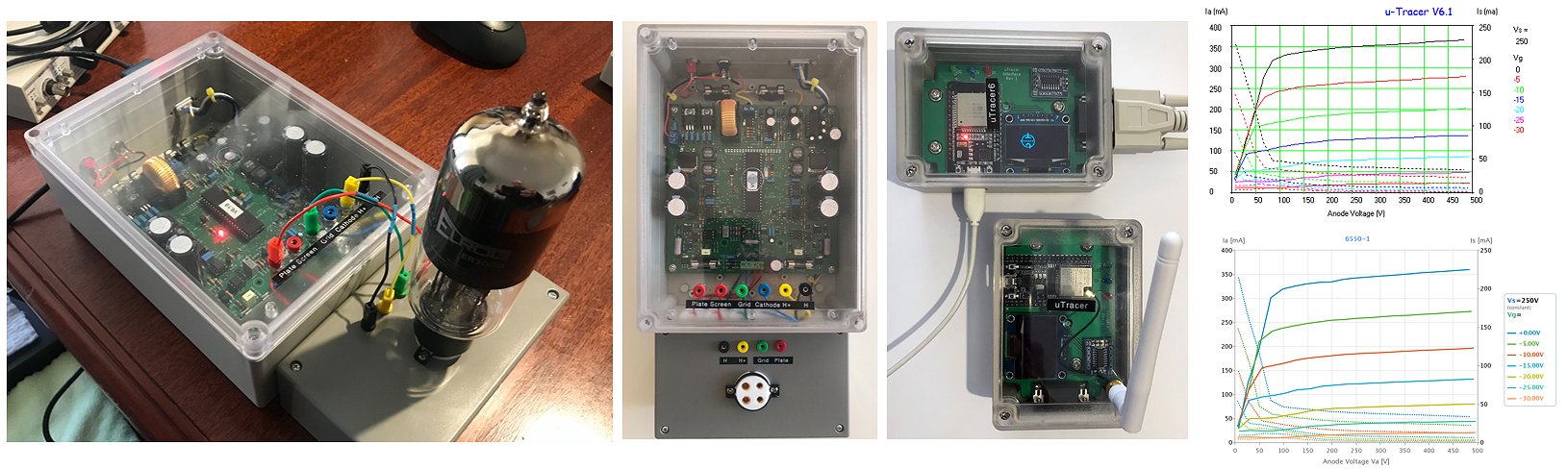
25th of August 2021 Dave is very pleased with his uTracer6 and used it to test a giant ELROG ER300B!
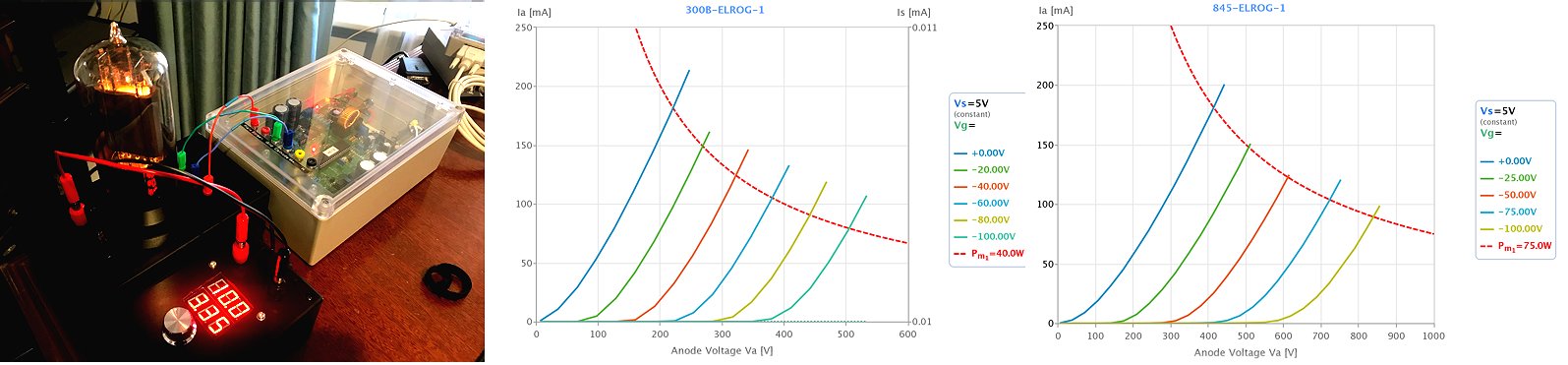
Hi Ronald, I can't thank you enough for the effort, years of experience, ingenuity and attention to detail that went into designing, productising the uTracer6 and turning into a kit.
The uTracer6 assembly instructions were again first class and I really enjoyed putting it together. Building it myself was part of the attraction.
As with my uTracer3 (which I'll still use for small tubes) I put the uTracer6 board into a simple plastic case with a clear lid so I can see the LEDs. Unlike the uTracer6 I haven't included any tube sockets. I'll build an external box for each tube-type with optimised anti-oscillation measures. You can see the 300B extension in the first picture.
The second picture shows a couple of Ihor Smal's ESP32-based units running his software. One of my original uTracer and one for my new uTracer6.
The only tubes that I currently have that can utilise the uTracer6's advanced capabilities are 6550s (and only just). I've attached pictures from both Ronald's software and Ihor's software.
I've ordered an XH-M403 DC to DC Digital Voltage Regulator Buck Converter for driving heaters beyond the capabilities of the uTracer6.
Thanks and regards, Dave.
25th of August 2021 Claes from Sweden reported his uTracer6 working!
Test setup with one vintage 6SN7, works now!
Made one mistake during calibration, cost one Mosfet in Anode HV ,T65. (hard to get).
Had a very god time during this trip. The instructions is great,
Next is to box it.
Report later boxed.
Best Regards
Claes Jansson, Sweden
3rd of July 2021 Shin-ichi from Japan turned his uTracer6 into a beautiful instrument with a redesigned heater supply!
Dear Ronald
It takes almost four months, and now I have finished assembling my version of uTracer6 based tube tracer.
Attached tracing.jpg is its figure !
I made build-in dc filament supply ( heater is also available, of course ) to trace direct heating tubes easy. This circuit refers to the PWM1 signal of uTracer6 to generate dc voltage that tracks the value of the Vh field of the GUI. Soft start ( This is a nice feature ! ) and on/off operation are controlled in the GUI's manner. Missing PWM1 pulse during measure period doesn't affect on filament voltage. A collage from my notebook (block.jpg) shows the simplified block diagram of this supply. A tiny flowchart of square root calculation gave me an inspiration about this circuit. This simple algorithm revives from 70's, the Cambrian period of eight bit microprocessors.
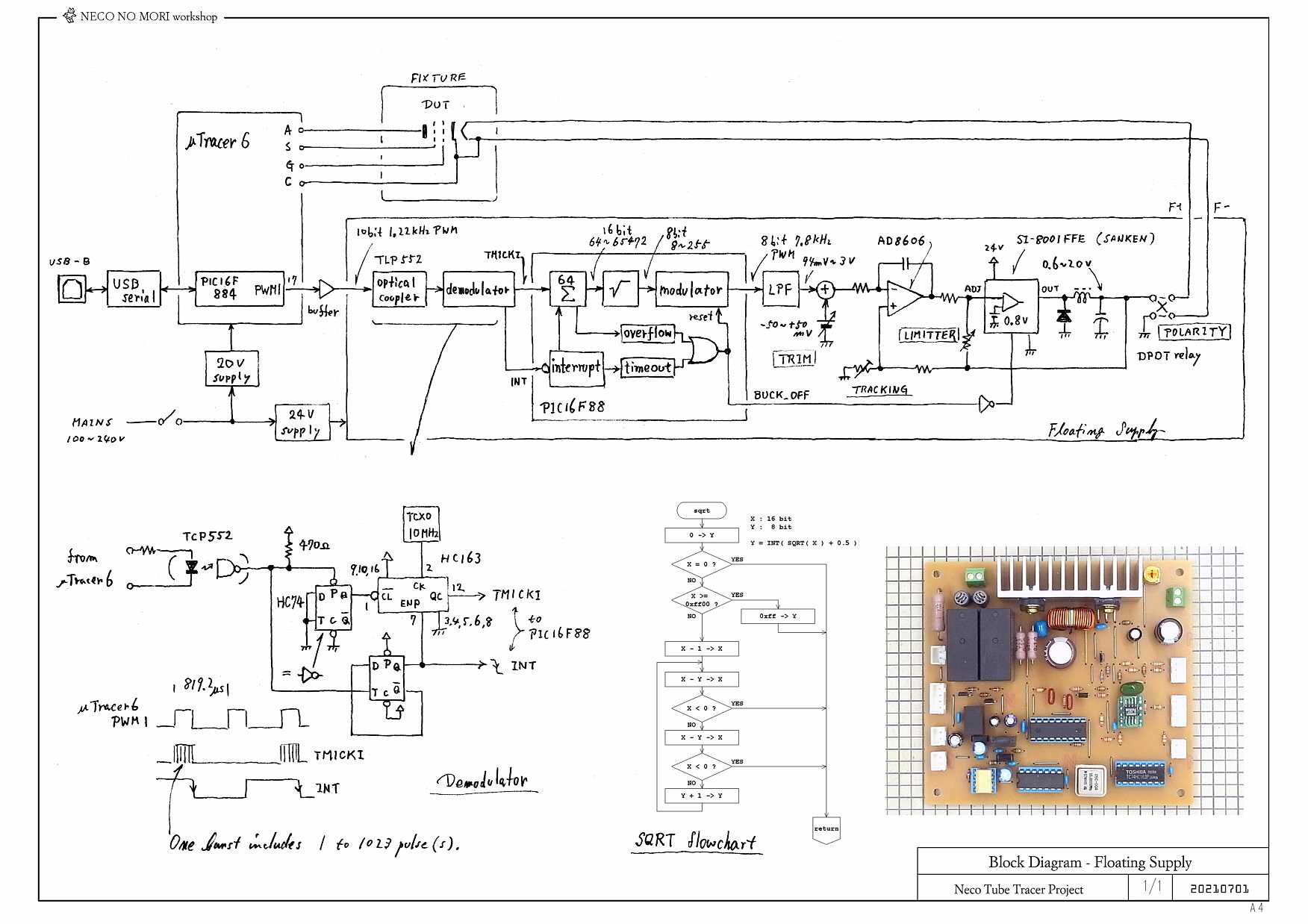
Inside the cabinet with uTracer6 is shown in interior.jpg. The floating supply board is positioned under the uTracer6 board.
The mainframe of this tracer does not have tube socket. A socket of required type is set on the fixture box as fixture.jpg shows. Pin selection is done in the box. Two types of fixture unit I made. One for MT sockets and another one is for larger sockets of GT, ST, compactron etc.
I thank you and uTracer6 !
Happy tracing !!
Shin-ichi
29th of May 2021 Jonas traced the “heaviest” tube so far on the uTracer6 a huge GU-78B!
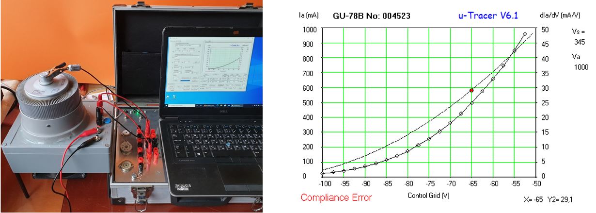
Hi Ronald and Marie-José,
I am very grateful to you for your adventure with uTracer6. 2021 May 29 The most powerful tube tested by uTracer6 is the GU-78B. The GU-78B is a Russian tetrode with a maximum anode dissipation of 2500W. The tube GU-78B requires forced air cooling, a fan is applied. Oscillations are suppressed and the tube shows a curve trace. In the attachment there are several pictures in the form of a report, for free use.
Best wishes
Jonas
1st of May 2021 Gary reported his uTracer6 working!
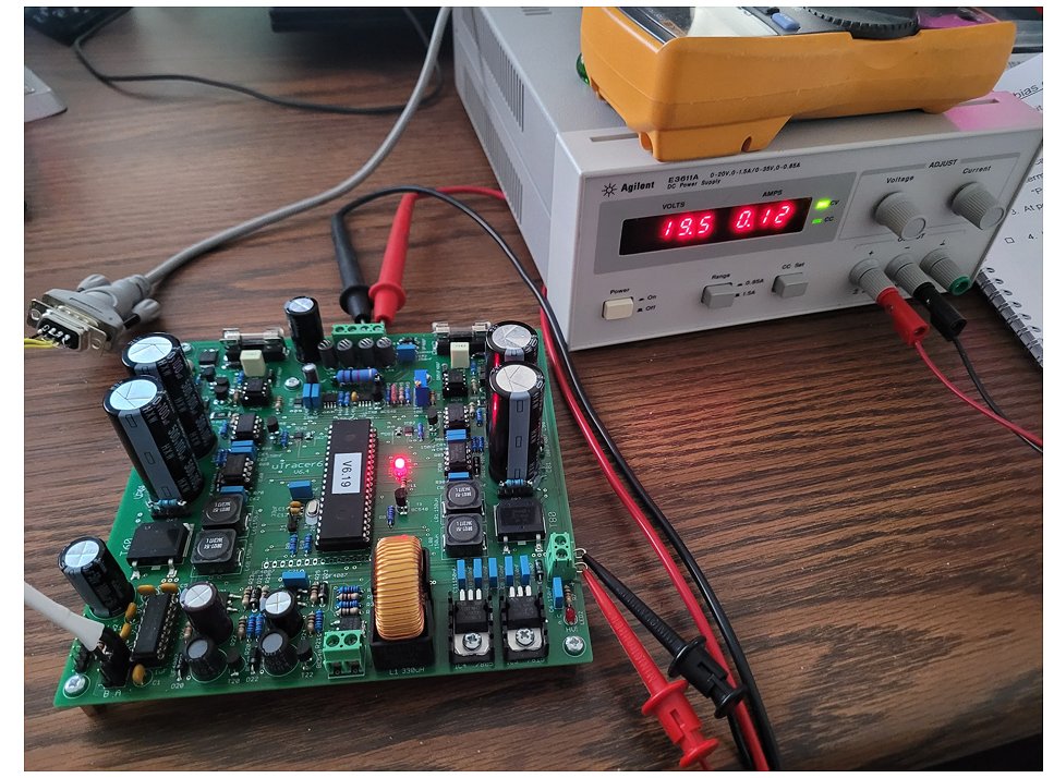
The uTracer6 kit went together nicely, and as usual the manual was superb.
I can't wait to give it an appropriate case and put it to use!
1st of May 2021 Winfried sent me a few pictures of the monster GU-81 he traced with the uTracer6!
The GU-81 is a Russian military pentode with a maximum anode dissipation of 450W. The heater alone dissipates 120W (12V @ 10A). A look at the datasheet shows that the uTracer6 can only trace a small part of the curves! Winfried traced the GU-81 both in pentode as well as triode mode.
Winfried sent me a beautiful present in the form of a 3D printed case for the uTracer6 complete with all the accessories and in our national color: orange!
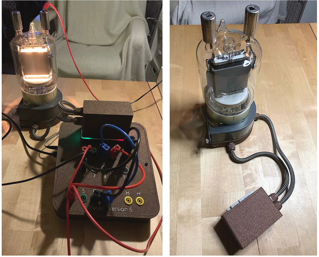
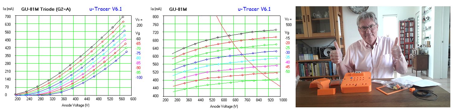
7th of April 2021 Francisco finished his uTracer6 and made a YouTube movie of it!
I have enjoyed so much building the new uTracer6 this weekend, and I gladly completed it without a problem. I have compared the results with my uTracer3 and they are exactly the same.
I attach some pictures and a short video.
Thank you again for this wonderful device.
Kind regards.
Francisco
5th of April 2021 Windfried designed a beautiful case around his uTracer6!
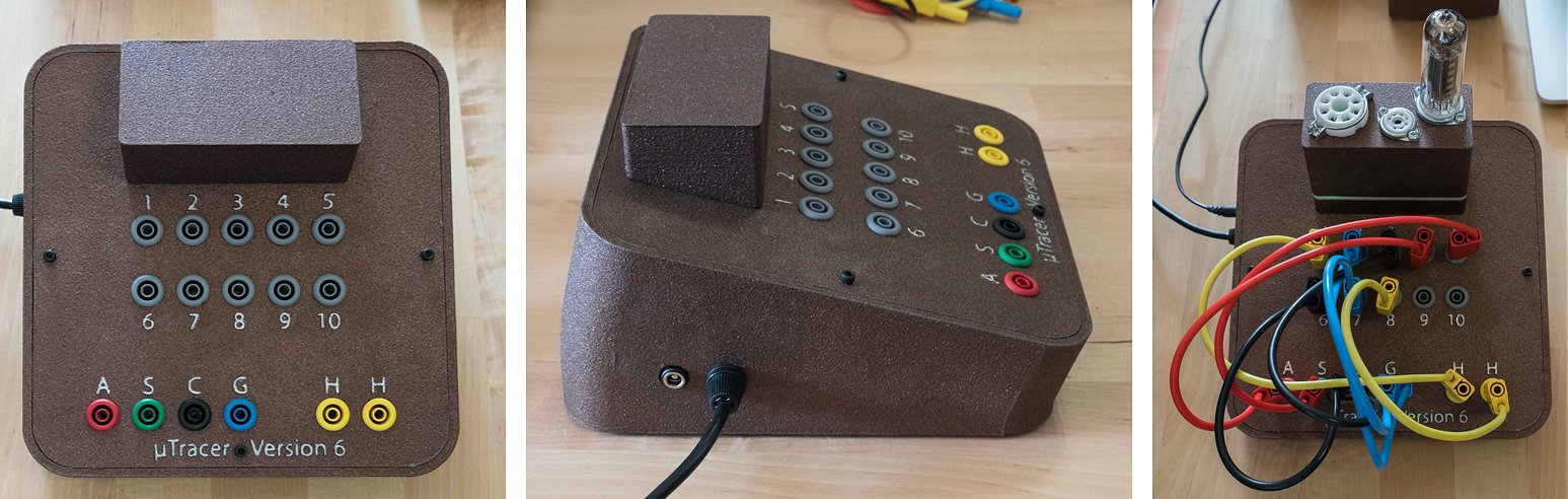
Happy Easter Ronald,
I finished my uTracer 6 and be back with the pictures. I already finished two tube adapters also (next will be one for GU-81 tubes probably :-).
You can see the indirect LED signals at the neck of the tube adapter socket (starboard and port accordingly with red signalling high voltage and green for power on).
I found another thing in the manual that could be corrected. At page 57 you recommend the use of a 330µH inductor wich is already included with the pcb/kit.
Best Regards,
Winfried
22nd of March 2021 Marcello from Itally finished his uTracer6 and immediately tested a massive WE 300B!
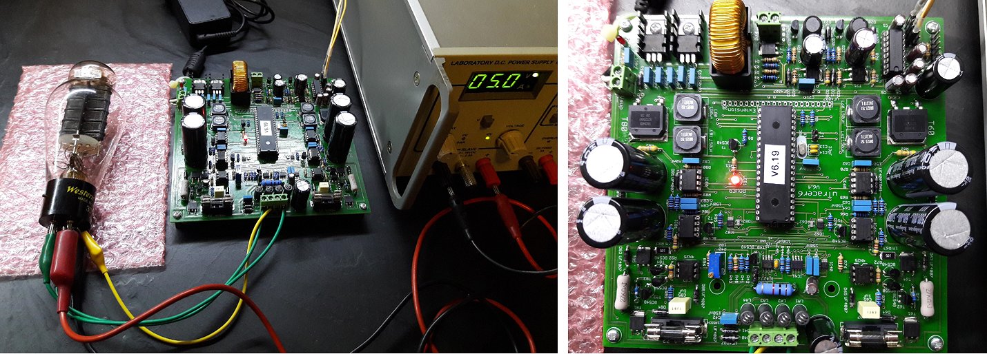
Dear Ronald and Marie Josč,
This morning I finished the uTracer 6, following the construction manual to the letter.
I did perform the calibration correctly, extending the calibration points to 600V, and all worked flawless.
Now I'm playing with some tubes, to familiarize myself with the instrument before closing in a proper case (external PSU yes/no... I think it will be necessary).
In any case, I want to thank you for designing and sharing this useful tool, essential to playing consciously with our beloved tubes.
All the best (from Italy)
Marcello
28th of February 2021 Shi-ichi from Japan reported his uTracer6 working, and his wife made a great compliment about the esthetics of the PCB!
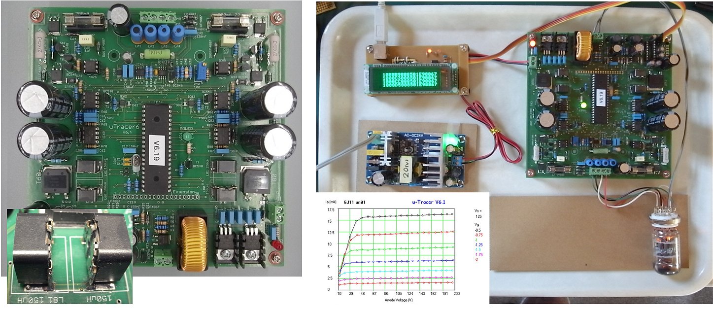
Dear Ronald & Marie-José
Thank you for your mail.
I attach two photos with this mail, the uTracer6 PCB I constructed and tracing scene. Please use them freely.
Add to my last mail, three modifications are applied to PCB.
LA1 through LA4 RFI suppression beads are covered by insulating sleeve and they are mounted on paper phenol resin sheet.
To avoid careless touching is the reason. They are tall.
Values of parts in the grid bias trimming circuit are changed.
R45 2M7 to 390k
P40 100ohm to 500ohm
The adjustment range was slightly narrow for my PCB condition.
Probably 200 ohm trimmer and 1M ohm R45 is better. But I don't have 200 ohm trimmer in my parts box.
POWER led is changed to green one. Simply because I usually use GaP green led for power indicator.
At this time, tracing is done on a lunch tray. This style is comfortable for experiment.
Upper left unit is USB to serial converter with command display. This unit includes TX/RX isolator by means of two photo couplers, to eliminate large ground loop.
A 6J11 dual pentode compactron is the DUT.
Measured plot image is collaged on the tray.
I am very satisfied with this result. Thank you Ronald!
When I understand enough about operation of this nice device, I will start designing the enclosure for uTracer6.
Yesterday, I showed uTracer6 PCB to my wife.
She said to me, "Mr.Dekker has his own aesthetics, I can feel it. This board is beautiful".
She is a graphics designer. I wish my modifications do not spoil your board design.
Sincerely
Shin-ichi
20th of February 2021 Roger Whigham finished his beautiful uTracer within a few days, encased and all!
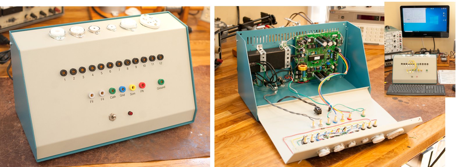
Hello Marie-José,
The kit went together very well. The instructions were clear and easy to follow. You and Ronald have done a great job putting this together. I really appreciate your effort.
I've attached some photos of the finished product. In case you're wondering, I built the chassis before I received the circuit kit. Although I've only tested a couple of 12AX7's, I haven't seen any oscillations yet. I'm keeping the snubber handy in case it is needed.
Thanks again for all your hard work.
Best regards,
Roger
19th of February 2021 Freddy from Germany is the first of the non-beta testers to report his uTracer6 working!
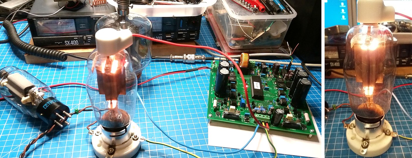
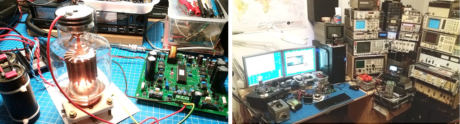
Hi Utracer v6 arrived today, I have assembled and calibrated, works great. I have tested RF Zero Bias Transmitting Triodes, Eimac 3-500Z Russian G811, American 811A , Cetron 572B , Svetlana 572B, and Chinese 572B up to 1 KV Anode and +120V Grid1 via screen Booster.
All measurements are equal to microtracer v3 biz only up to 400 volts and 600 mA current after modification. The next day I will test some audio tubes el 34 el 84 6l6 6p3s kt66 and some double triodes ecc 83 85 88 and Russian equivalent 6n1p 6n2p and 6p3s.
Thank you and have a nice day
Freddy