At the moment more than 2800 uTracers are in service in 66 countries! In most cases the building of the hardware didn’t cause any serious problems. In contrast most issues appear to be related to the (installation of) the GUI. For most of these issues solutions or workarounds have been found. In this section I have listed the most common issues and or questions. Some of the issues and solutions listed here have been contributed by others for the simple fact that the problems did not occur on my test computers. Please contact me if you have any additional tips and or suggestions which might be useful for other users!
Frequently asked Questions:

General:
GUI related:
Other operating systems:
Hardware and construction related:
Operation of the uTracer:
General items
I have a problem / question, where to turn to?
If you want to order a kit, have a technical problem or question of any sort, or want to send me a testimonial or photos of your uTracer, please mail me directly at Ronald@dos4ever.com.
Please use the uTracer@dos4ever.com account only for questions concerning shipment and finances.
You will not find me on forums or internet groups, I do not like them, sorry.
How about all these uTracer versions?
The hardware versions:
| uTracer 1 |
This version never made it further than some exploratory experiments. The experiments are recorded in this Weblog (sections 1-7) |
| uTracer 2 |
This version was completed into a working prototype. It used the grid of the tube to switch the anode current on and off and it used a rather curious construction with capacitors to measure the currents. It didn’t perform the way I wanted and the project was abandoned. The experiments are recorded in this Weblog (starting from section 8) |
| uTracer 3 |
The first commercial (300 V) version of the uTracer. The uTracer website is devoted to this version. The experiments and development work leading to the uTracer 3 are recorded in this Weblog The Graphical User Interface software controlling the uTracer 3 is GUI 3 (all subversions) |
|
uTracer 3+ Obsolete |
This version is almost identical to the uTracer 3 but has an extended high voltage range of 400 V. This version replaced the uTracer 3 in December 2014. A uTracer3 can easily be converted into a uTracer 3+. Instructions for this conversion can be found Here. There is a small conversion kit available with the necessary components. The experiments and development work leading to the uTracer 3+ are recorded in this Weblog (sections 31 and 32) The uTracer 3+ requires GUI version 3.11 or higher (see below)! Over the years, it became more and more difficult to source components for the uTracer3+, so in October 2026 we stopped selling the uTracer3. It has now been succeeded by the uTracerNXT (see below). |
| uTracer 4 |
The idea of this version was to use transformers to generate measurement voltages in excess of 1 kV. The whole idea turned out to be more complex than originally planned so the project was abandoned. The experiments for the uTracer 4 are recorded in this Weblog. |
| uTracer 5 |
The idea for the uTracer5 was to create the ultimate tube curve tracer with and anode and screen range of 0 to 900V at 1 A current, negative and positive grid biases and a programmable true DC heater supply. In the end the project just became too complex and I abandoned it. However, much of the ideas found their way into the uTracer6! The experiments for the uTracer5 are recorded in this Weblog. |
|
uTracer 6 available now! |
The uTracer6 was the first real new version of the uTracer that was introduced mid 2021! The uTracer6 is a good compromise between performance and complexity. It offers 1000V / 1A anode and screen capability combined by a 0 to -100 V grid supply. At a later stage an extension board with a 0 to +100 V grid supply will become available (including grid current measurement). For a comparison between the uTracer3+ and the uTracer6 see the entry below.
The experiments for the uTracer6 are recorded in this Weblog. |
|
uTracer 7 Ideas, thoughts and experiments |
With the 1000 V / 1 A uTracer6 now available as kit, there is still a demand for a uTracer that can go to even higher voltages, especially by Ham radio enthusiasts. I have no idea is such a device is practically and economically feasible, but it is a challenge to think about possible concepts that can enable the 5000 V/ 1A range (pulsed of course).
The ideas, thoughts, and experiments for the uTracer7 are recorded in this Weblog. |
|
uTracerNXT available now! |
The uTracerNXT is positioned as the successor of the uTracer3+. It uses more modern, readily available components and implements circuits learnings gathered over the past ten years with the uTracer3+ and the uTracer6. It offers anode/screen voltages up to 500V @ 350 mA, with a grid voltage down to -120 V. The uTracerNXT can easily be “personalized” for higher currents (up to 1 A), lower voltages (e.g. for battery tubes), or improved resolution using the “My-uTracerNXT” concept.
The ideas, thoughts, and experiments for the uTracerNXT are recorded in this Weblog. |
How many uTracers are there in operation?


Should I buy a uTracerNXT or the uTracer6?
For your convenience I have the most important characteristics of the uTracerNXT and uTracer6 listed in the table below and compared them to the now obsolete uTracer3+.
| Characteristic: |
|
|
|
|---|---|---|---|
| Status |
|
|
|
| Anode and screen supplies |
|
|
|
| Grid supply | Voltage range: -50 V to 0 V | Voltage range: -120 V to 0 V |
Voltage range: -100 V to 0 V An extension board (grid shield) is available that extends the grid bias range to positive grid biases 0 V to +100 V, including grid current measurement 0 – 100 mA. |
| Internal heater supply |
Voltage range 0 – 19.5 V (max. 1.5A) The heater supply PWM modulates the supply voltage at a frequency of 19.5 kHz. Due to this relatively high PWM frequency parasitic inductances in the leads will result in a lower effective heater voltage. For this reason, many users prefer to use an external heater supply. |
Voltage range 0 – 19.5 V (max. 1.5A) Compared to the uTracer3 the PWM frequency has been reduced to 1.2 kHz. This makes the effective heater voltage virtually insensitive to parasitic wiring inductances, resulting in more accurate heater voltages. |
Voltage range 0 – 19.5 V (max. 1.5A) Compared to the uTracer3 the PWM frequency has been reduced to 1.2 kHz. This makes the effective heater voltage virtually insensitive to parasitic wiring inductances, resulting in more accurate heater voltages. |
| AC heater supply supported? | No . |
An AC heater supply (transformer) for directly (and indirectly) heated tubes is standard supported. Read more |
AC heater supply for directly heated tubes is possible with a small (user made) additional circuit. Read more |
|
Extensions, Options, Personalization | There is an extensive set of modifications and options for t the uTracer3+ available (see next FAQ). However, they are all add-on circuits that users must make themselves. . |
Extensive possibilities to personalize the tradeoff between ranges and resolution have been directly incorporated into the design of the uTracerNXT, e.g. for higher currents, more accurate grid voltages or low anode/screen voltages for battery tubes. Read more in the “My-uTracerNXT” guide. |
There is an extension board (shield) available for the uTracer6 that allows for positive grid biases (0 – 100 V) and the measurement of grid current (0 – 100 mA). Read more |
| Maturity | With more than 2700 uTracer3 units in operation in over 64 countries, the uTracer3 was a successful and well debugged kit. The experiences with the uTracer3 provided valuable input for the development of the uTracer6 and uTracerNXT | The newcomer uTracerNXT builds on the extensive experience gained with the uTracer3+ and uTracer6. | More than 550 uTracer6 units have been constructed without significant problems. |
| Application range | The uTracer3+ was primarily intended for low/medium power tubes used in the driving stages of amplifiers, radio’s, and televisions. | The uTracerNXT covers the applications range of the uTracer3+, but with its higher voltage and current range and control grid voltage range down to -120 V, it now also covers power (audio)amplifier tubes. | Although the uTracer6 can also test and trace low power tubes, its application range are primarily medium and high- power tubes such as encountered in audio output stages and RF transmitters. Especially the possibility of positive grid voltages (including grid current measurement) will be appreciated by ham-radio enthusiasts. |
| Robustness |
Overall, the uTracer3+ has proven to be a robust design. Nevertheless, points for improvement are:
| ||
| Price: | Not applicable |
|
|
| Conditions of sale | Price includes: shipment worldwide and assistance with construction including mail support and physical debugging of the unit if needed in incidental cases. PCB with SMD components assembled, all other components (difficult to identify components in labeled bags), and a printed and bounded manual. Not included are: USB to serial cable, 19.5 supply (old laptop power supply), tube sockets etc. | ||
Are there any extensions available for the uTracer3+ ?
Yes! As it turns out the uTracer is an ideal platform for further experimenting! Over the time I have investigated and published several extensions that either extend the measurement range of the basic circuit or that make it useful for other applications. Most of these extensions only require a small additional circuit that can easily be built on a piece of perfboard which can be added to your uTracer hardware. You can find most of these extensions on my “Lab Notebook” page, but for convenience I have listed them here:
Higher anode and screen currents Click Here
With only a few components modified and a new release of the GUI you can increase the current range for the anode and screen channels to up to 1A!
The circuit requires GUI version 3.12.6 or higher
(Click Here)
More accurate low and even positive (!) grid voltages! Click Here
A small add-on circuit that allows you to accurately generate low grid voltages. In contrast to the standard grid voltage circuit of the uTracer, this circuit can deliver currents which improves the accuracy around 0V. Additionally the circuit is able to generate positive grid voltages.
The circuit requires GUI version 3.12.3 or higher
(Click Here)
Measure gird currents for positive grid biases! Click Here
A slightly more elaborate circuit compared to the previous one not only allows you to apply positive grid biases, but also to measure the resultant grid current.
The circuit requires GUI version 3.12.3 or higher
(Click Here)
Test and re-form vintage electrolythic capacitors with your uTracer! Click Here
With a few resistors and diodes you can turn your uTracer into a useful device to test and re-form the electrolytic capacitors from your vintage equipment. In many old capacitors it can restore the thin dielectic bringing them back to life again.
The circuit requires GUI version 3.12.5 or higher
(Click Here)
Use your uTracer to measure the characteristics of transistors! Click Here
With a handful of resistors and a rotary switch you can use your uTracer to trace the curves of NMOS and NPN (high-voltage) transistors.
Runs with all GUI versions.
Run the quick test via Bluetooth from your Android app! Click Here
This contribution from the son of a uTracer owner allows you to run the quicktest from an app on your Android tablet or phone. The contribution also describes how you can connect your uTracer with a blue tooth connection.
I want to know more about how tubes work.
If you want to know more about how tubes work have a look at this chapter from the Radio Handbook 1967 suggested to me by peter Bulanyi.
Questions related to the (installation of) the GUI
I have problems installing the GUI.
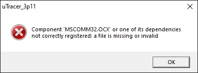
Normally installing the GUI should be straightforward. Just unzip the download to a temporary directory. There are three files in the unzipped download: a CAB (cabinet) file, a LST listing file and a Setup application. The CAB file is just another zipped file which contains the GUI executable and some ActiveX components (.OCX files) the executable needs to run. Most important are the mscomm32.ocx and MSCOMCTL.OCX which deal with the serial communications. Normally double clicking the “SETUP” application should be sufficient to install the program and register the new components in the registry. I have used the standard Visual Basic “Package & Deployment Wizard” to create the installation package, and it should work fine. However, in practice sometimes some difficulties are experienced.
Worst case the “Setup.exe” installer supplied with the download doesn’t work at all. What you can do in that case is to create a directory “uTracer3px” in your “Programs Files” directory (for XP) in the root of your system by hand. For Windows 7 this directory should be located in the “Programs Files (x86)” folder. Simply unzip the CAB file into this directory. With a bit of luck the necessary OCX components have been already installed and registered in the past by some other program, and the GUI will run by simply double clicking the executable: uTracer3px.exe. Most of the time, however, one or two OCX components are missing and they will need to be installed by hand. In the next section you can read how this can be done. Manual installation of these missing files is also required when during the normal setup procedure the following message is displayed:
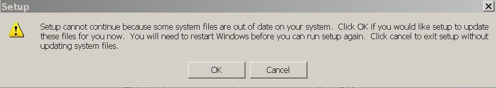
During installation I get the message “files are out of date” (see above)
Since this has never happened on one of my own systems, so I can only relate of the solutions others have found! The error message is probably related to a problem with your registry!
The first thing to do is to check if setup application has made a directory “uTracer3px” in your “Program File (x86)” directory. If not, you will have to create it yourself, and unzip the uTracer3px executable into it (see previous section).
Next the missing components need to be installed. Joe Neil has given me a description of how this can be done manually:
In order for this app to work, you need to "register" mscomm32.ocx with regsvr32.exe.
You should be able to do this with a command line but sometimes that doesn't work. Here's an alternate way:
For Win XP, regsvr32.exe should be in the \WINNT\system32 folder. mscomm32.ocx should be there as well, but you may need to download it.
I got it here http://www.nodevice.com/dll/MSCOMM32_OCX/item12152.html
To "register" mscomm32, put your cursor on the mscomm32 file, hold the left mouse button down, "drag" the file on top of the regsvr32 file, and release the button (drop). You should get a window that mscomm32 has been successfully registered.
Chris Bartnick had the same problem and found a more thorough way to solve the problem.
He was so good to write an email with a step-by-step recipe, which is repeated below. Thanks!
I wanted to install the GUI on a dedicated desktop with a new Windows XP Home Edition with SP3 installed. The hard drive was formatted for a clean windows installation. Upon installing the GUI, I got the dreaded message "some system files are out of date on your system". I have service pack 3 installed. There are no newer registry files that I am aware than those in SP3. Then I tried to install it to a working laptop with Windows XP Proffessional SP3 with same result. I tried to do it manually as described by Joe Neil in FAQ. It was confusing because my XP installations had no \WINNT\System32 folder. That folder exist only if one migrated from Windows 2000 or NT. Anyway, after hours of research on the internet I got it installed and it is running fine on both computers. A step by step guide is below. I will post it also in the Google Support Group.
You'll see the following sub-folders:
/uTracer_v3pxxxx/uTracer_3pxxx/Package (xxx are the version numbers or whatever).
Left-click on Package > left-click on .CAB file,
> highlight all files and right-click them > Extract to directory C:\Program Files\uTracer3px. you just created.
Change directory to C:\Program Files\uTracer3px.
There will be several files, among them MSCOMM32.OCX and MSCOMCTL.OCX.
Drag them into the C:\Windows\System32 folder.
Close windows explorer.
Click Start > Run: type "command" in the window, do not hit ENTER yet, push CTRL+Shift keys and now ENTER key, click YES
in the black command window change directory: cd C:\Windows\System32, make sure C:\Windows\System32 is shown at the prompt.
Type command: regsvr32 /u MSCOMM32.OCX (Note: there is a space after 32) and hit ENTER, this will unregister the file, click OK.
Repeat this for the MSCOMCTL.OCX file,
Type command: regsvr32 MSCOMM32.OCX this will register the file.
Repeat this for MSCOMCTL.OCX file. Click OK.
Type exit + Enter to exit the command window.
All this is shown again here:
http://scn.sap.com/people/firoz.ashraf2/blog/2014/10/02/how-to-registeractivate-activex-component-mscomm32ocx-on-windows-7
In windows explorer go to C:\Program Files\uTracer3px and right-click on uTracer3px.exe > Send To > Desktop.
Done.
During installation on Windows 10 I get the message “run-time error 52”
A contribution by Yehuda
I wanted to install the GUI on a Dell laptop running 64-bit Windows 10. Upon installing the GUI, I got the message "Run-time error ‘52’". I tried to do it manually as described by Chris Bartnick in FAQ. But it didn’t work because when I registered the .OCX files I received the message:
In order to solve the problems I’ve done the following steps:
After unzipping the uTracer GUI package right-click on .CAB file and choose ‘properties’. If you see at the bottom of the ‘general’ tab the massage: “This file came from another computer and might be blocked to help protect this computer” you need to click the “unblock” button.
Next create a new folder "uTracer3px" and extract the files in the .CAB folder to the directory you just created.
If you are using 64 bit version of windows you need to copy the .DLL, .OCX and .TLB files to c:\Windows\SysWOW64 folder. Keep the newer files, if they are already installed in the SysWOW64 folder.
Next the .OCX files need to be registered in the Registry with the following procedure: Click Start and run "command prompt". In the command window change directory: cd C:\Windows\SysWOW64, make sure C:\Windows\SysWOW64 is shown at the prompt. Type command: regsvr32 MSCOMM32.OCX (Note: there is a space after 32) and hit ENTER, click OK. This will register the file.
If after entering the command you receive the following massage:
You need to open the “command prompt” in administrator mode. Right-click Command prompt and then click run as administrator.
In the command window change directory: cd C:\Windows\SysWOW64. Type command: regsvr32 MSCOMM32.OCX and hit ENTER, click OK.
Repeat this for the MSCOMCTL.OCX and ComDlg32.OCX files.
Type exit + Enter to exit the command window.
Finally create a shortcut to uTracer program.
In windows explorer go to the uTracer3px folder and right-click on uTracer3px.exe > Send To > Desktop.
Done.
What is the default location where the GUI stores the measurement and plots and the calibration file ?
Windows XP:
 The location where the calibration file is stored, and the default location where plots and data files are stored is in the same folder where the executable is stored. If the normal installation procedure is followed this is:
"C:\Program Files\uTracer3px”
Windows 7 (adapted from Nick de Smith):
If Windows 7 has the User Account Control (UAC) feature enabled (the
default) then any attempt by an application to write to system directories is secretly re-directed to a user-specific "virtual store"
that is read/write for that user - this is done to prevent users from corrupting installed applications - the same thing has been done on UNIX for years...
The default location for your virtual store is:
"C:\Users\<username>\AppData\Local\VirtualStore\Program Files" or "C:\Users\<username>\AppData\Local\VirtualStore\Program Files (x86)"
...where <username> is your login username. The virtual store is designed to shadow the directory structure under "C:\Program Files" but is qualified by the login username... Note that if you are running 32-bit Windows 7 or have some 32-bit applications installed, you will see the "Program Files (x86)" directory - 64-bit Windows 7 uses the "Program Files" directory - for convenience, the rest of this document will refer to "Program Files" to mean whichever of the two possible directory trees uTracer was installed under.
Note that the "AppData" directory is, by default, hidden from view as its a system folder - you can make it visible in Explorer by navigating to "C:\Users\<username>" then from the "Organize" menu select "Folders and search options". From the dialogue box that then pops up, select the "View" tab. In the "Advanced setting" window under "Hidden files and folders", select the "Show hidden files, folders, and drives" radio button - then click "OK"....
Under the "Program files" directory above, you will see a further directory called "uTracer_v3px". The calibration file and plot/data files are stored in this folder.
I do not like your GUI! Is there another option ?
Yes! Nick Barton has written an alternative GUI. He Christened it “uTgui.” uTgui is written in C++ using the QTclass libraries. It a user- extensible tube database of settings and pin outs, and plots can be saved in pdf format. Nick is building a SPICE library of models that includes every tube that he comes across. That library is included in the binaries download. Another significant point is that he communicated with Norman Koren and got his permission to use his models. Nick extended the pentode models to include better screen current simulation and added a super-sharp pentode knee version. You can read about the development on the Google uTracer Group. The code is also available on the website of his company Black Magic Amplifiers.
Where can I find information on the communication protocol ?
The communication protocol is described in the original weblog. For the GUI 3p11 I have published the blocks of VB code that takes care of the communication with the uTracer. For GUI version 2.12.3 you can find the code blocks here.
How to migrate the GUI from version 3p10 (or 3p9, 3p8) to 3p11 ?
If you have already installed version 3p10 (or an older version), and have it up and running, you do not have to go through the whole installation procedure again because all the necessary (OCX) components have been installed already. Simply create a directory, preferably in the “Program Files” (Windows XP) or “Program Files (x86)” (Windows 7) directory, with a suitable name (e.g. uTracer_3p11), and unzip the “v3p11-executable-only-zip-file” (available on the download page) directly in that folder. Double click the executable and it should work.
To transport the calibration values from an older GUI version, simply copy the old calibration file into the newly created folder and run the GUI 3p11. The GUI will detect the calibration file and translate it into a new calibration file for the version 3p11.
The GUI won’t install on a 64 bit machine.
A contribution by Ernie Herrera
After installing the GUI, attempt to open the program runs another application.
i.e. “click to install Windows Office Pro Plus”,
The uTracer3 program was setup to install using visual basic for 32 bit machines. Windows 64 bit machines can run 32 bit apps ok, but sometimes existing 64 bit apps get in the way executing calls from the machines memory.
There are two ways around this problem:
Easy Method:
First, un-install the complete 64 bit application that runs in place of uTracer. Then uTracer will run OK. Then re-install a 32 bit version of the program you just un-installed. The uTracer should still run ok.
This worked for me, and no subsequent problems.
Advanced, more elegant method:
.Net Common Language Runtime (.net CLR) is a manger on Windows 64bit versions that supports Visual Basic . It is set by default “false” - enable 32 bit applications. We need to set enable to “True”:
- Go to Start, Search, type “windows features” and from the menu highlight/ enable “Internet Information Services”. Click ok and the inetmgr will install.
- Then go to start/run and enter inetmgr. On left arrow find and click on “Application Pools”, then “Default App pool”, then “Advanced Settings”.Click on “32 Bit Applications” and toggle so it reads “True”. Click OK.
- Un-install uTracer, and reboot.
- Now re-install uTracer. That’s it.
- https://www.youtube.com/watch?v=PjbV-PQycT8
Error “ComDlg32.OCX and MSCOMM32.OCX missing” during installation on Windows10.
Solution 1: A contribution by John Walton
In Microsoft download: Microsoft Visual Basic 6 Service Pack 6 Cumulative Update
https://www.microsoft.com/en-us/download/details.aspx?id=7030
Or if the link is broken, simply search for “Microsoft Visual Basic 6 Service Pack 6 Cumulative Update”
It will place the MSCOMM32.OCX and other files in the registry.
Solution 2: A contribution by Sven Stalbovs
Trying to install/run uTracer_3p12p6.exe as administrator on Windows 10 64-bit German version the following happened. First error came up:
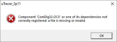
After some research and try and error it came to the point that none of the Google search results including Microsoft gave the complete answer but the right direction in order to register this missing file.
Problem was to get the right file. With files downloaded from the internet to register there was always a compatibility error which inhibited the registration.
Therefore I extracted the file from the Microsoft software package Visual C++ 6.0 Professional Edition.zip.
Download these files here.
The file needs to be placed into directory C:\Windows\SysWOW64\
Then run as administrator Windows PowerShell and the command
PS C:\WINDOWS\SysWOW64> regsvr32 C:\Windows\SysWOW64\comdlg32.ocx
This time the registration was confirmed as successful.
Again trying to install/run uTracer_3p12p6.exe
a second error came up:
From the same package mentioned above this file was put to the Sys_WOW64 folder and following command was successful:
PS C:\WINDOWS\SysWOW64> regsvr32 C:\Windows\SysWOW64\mscomm32.ocx
Then uTracer worked and created a new .cal file. Wow, I am happy.
How can I find/assign a COM port number in Windows11?
You can check what device is using what COM port from the Device Manager. It will be listed under the hidden devices!
From de Device Manager, select View – Show Hidden Devices.
Now, when you expand the (PORTS) COM ports section, you will see all of the COM ports listed there.
To check what port is used by what service, open Device Manager, select the COM port, right click and then click on Properties/Port Settings Tab/Advanced Button/COM Port Number drop-down menu and assigned the COM port.
Starting from COM1 and changing to COM2, etc. for each device, you can assign Ports to each device.
The uTracer does not respond to the setting of the slider.
I have noticed that in some configurations of Windows, the value at the position of the slider (A), is not always copied to the recorded value at the right (B). Keep an eye on this and if this does not happen, click on the slider again!
Questions related to the use of the GUI under other operating systems
Configuration of the COM port in Wine
A contribution by Glenn!
Starting from Wine 2.8, the simple symlink-editing method of port configuration doesn't work.
You have to use the Wine registry to change COM ports:
wine regedit
Then work through the registry tree to HKEY_LOCAL_MACHINE\Software\Wine\Ports
Then create a new string value, it's name should be the com port, e.g. 'COM1'; and the string value should be the path to the actual linux device, e.g. '/dev/ttyUSB0'
The entry should look like the example above. If all is OK, quit regedit.
After editing the registry, shut down Wine:
wineserver -k
The next time Wine runs a program, your changes will take effect.
Don't forget that you must also be a member of the 'dialout' group to be able to properly manipulate the com ports. If in doubt, you can issue the command:
sudo adduserdialout
Does the GUI run under Oracle’s Virstualbox (under LINUX) ?
Marcello Borini tested the GUI in Oracle’s Virtualbox on a PC running openSUSE Linux 13.2-64. He found it worked fine, and wrote a nice document on the details of installation of the serial port (click here)
Can I run the GUI on my Mac ? (Part I)
I am not at all the expert in this, but Martin Manning has figured out a way to run the GUI successfully on his Mac. He was kind enough to share his experiences with us!:
I have the uTracer GUI running in a Windows 8 environment which has been installed on a partitioned section of the MacBook’s hard drive. The partition was created with the help of Apple’s Boot Camp software, which is available at no cost from Apple. A copy of the Windows OS is also required, and this can be purchased from any number of sources for about $100 US. In this scheme, switching from OSX to Windows requires a shutdown and restart. There are other ways to do this (Parallels, e.g.) where both OSX and Windows can run simultaneously, but that convenience comes at the cost of sharing processor and memory resources between the two OS.
Apple’s instructions for installing Windows using Boot Camp are quite extensive (see http://www.apple.com/support/bootcamp/), but there were a few things that weren’t immediately obvious to me. Boot Camp Assistant, which is found in the Launch Pad area under “other,” walks you through the process, traps errors, and provides links for downloading the support software and instructions. A printed copy of the instructions is recommended since the on-line instructions won’t be accessible during the installation.
The following are some additional tips I can offer based on my experience:
- The first step is downloading the current version of the Boot Camp support software from Apple, which contains the drivers for Apple peripherals. I recommend copying this download onto a flash drive for ready access when the Windows OS is initially installed and running. Files can be shared across the partition, but placing them on a flash drive is simpler because you will know exactly where to look for it.
- An MS-DOS (FAT) formatted 8 GB flash drive must be inserted before the installation is started. FAT is the standard format for such devices, so no action is required other than inserting the drive into an available USB slot. The Boot Camp support software can be loaded onto this same flash drive ahead of time as described above.
- The Boot Camp Assistant instructions talk about creating a flash drive with a Windows ISO image. The Windows OS copy I bought, however, came on a DVD. Near the beginning of the Assistant process a window with three media options appears, with all three of them checked by default. For my case, I had to un-check the first two, leaving only the third, which is installing Windows from a disk.
- A “Custom” Windows installation must be performed. The Boot Camp volume must be selected and then formatted in NTFS before proceeding, and this step is well documanted in the instructions.
- After the installation finished, I had to open the Boot Camp folder on the flash drive and run setup.exe, which got me a to a fully-functional system. There are numerous options for setting personal preferences (screen brightness, trackpad settings, etc.), as well as the default OS for start-up, which are detailed in the Boot Camp instructions.
At this point I downloaded the uTracer v. 3.8 GUI and installed and ran it with no issues, and similarly for the v. 3.10 executable.
Can I run the GUI on my Mac ? (Part II)
The question how to run the uTracer GUI on a Mac system seems to continue puzzling people! Mike Foo found a way to use the uTracer GUI on a Mac system, without resorting to booting into Windows via bootcamp. Here is his account of the procedure.
I managed to get uTracer ver 3.10 working in Mac OS. I can stick to Mac OSX and yet run uTracer. I use WINE.
- Download and install Wineskin Winery. Download one of its engines and one of its wrappers also. ( http://wineskin.urgesoftware.com/tiki-index.php?page=Downloads).
- Run the Wineskin Winery application and select "Create New Blank Wrapper" to create an empty wrapper. Give the wrapper a name when prompted (Eg. uTracerGUI.app). The wrapper wraps around the windows application with a pseudo Windows environment.
- Once the blank wrapper has been created, execute the wrapper.
- Since it is still an blank wrapper, install the uTracer software using the "Install Software" option. Select "Setup.exe" from the uTracer installation files.
- Once the uTracer software has been installed, the next step is to setup the communications interfaces for the uTracer hardware.
The uTracer software will have to use COM ports to communicate to the uTracer hardware thru the Mac's recognised communication devices. - In my setup, I'm using the FTDI USB to Serial cable to interface with the uTracer. I need to find out what this device is listed as in my Mac. To check, I open "Terminal" and type in "ls -l /dev/". This will list all the available devices in my Mac.
- Fortunately, I see only two devices related to USB Serial, namely "cu.usbserial-FTTE9TWP" and "tty.usbserial-FTTE9TWP" appearing in the list. I do not know which one represents my USB Serial cable, so I proceeded with the next few steps by trial and error.
- Now the WINE wrapper creates a Windows environment for the uTracer GUI. The devices that has been defined for the Windows environment is shown in /Applications/uTracerGUI.app/Contents/Resources/dosdevices. In "Terminal", change to the "dosdevices" directory. There shouldn't be any COM port defined yet.
- I wish to use COM3 port to communicate to the uTracer software. So I define a COM3 device as a symbolic link in the "dosdevices" directory to the USB Serial device listed in my Mac's /dev/ directory.
- So while I'm in the "dosdevices" directory, I type "ln -s /dev/cu.usbserial-FTTE9TWP com3". I would need Root privilege on my Mac to do this.
- After this when I list "dosdevices" directory, I should see "com3" and it is a symbolic link to /dev/cu.usbserial-FTTE9TWP on my Mac.
- Now when I run the uTracerGUI.app, I select COM3 port to communicate with the uTracer hardware. So whenever data is routed to COM3, it is actually routing to the USB serial. If this doesn't work, I will try linking COM3 to "tty.usbserial-FTTE9TWP" instead.
Mano found that some additional changes were needed to make it work with the FDTI USB <-> Serial converter chips Click Here.
Can I run the GUI on my Mac ? (Part III)
Another set of instructions that explains more graphically how to run the uTracer GUI on Mac OS using WINE was provided by Clemens Mug. Click here to download the pdf file.
Can I run the GUI on my Mac ? (Part IV)
Johannes Specht had difficulties to make the GUI to communicate with his USB/FTDI adapter in Mac OSX.
Read here how he solved the problem, and for step-by-step instructions on installing the GUI.
Questions related to the hardware, or construction of the uTracer
Where can I buy good tube sockets ?
Since I had no idea (I always use sockets from my own stock) I asked the people on my uTracer mailing list. The result can be found on my Tube-Tester Links page. Very worthwhile a visit, also for other stuff!
I do not pass step 5 of the construction manual “Micro-controller testing.”
In some cases, people successfully complete stage 4 (RS232 interface testing) of the construction manual, but then get an “Error, uTracer failed to echo character in reasonable time” error at stage 5 (microcontroller testing). Most people immediately suspect that they have a defect PIC controller, but this is almost never the case. Every PIC processor is programmed by hand and individually tested in a test uTracer before being shipped.
Let’s take it step by step. Passing step 4 only means that there is a succesfull back and forth communication through the MAX232 transceiver. However, this can be at any baudrate, parity bit setting or other critical communication parameters, since the Tx and Rx channels are probably initialized to the same settings. If these settings to not match the requires 9600 baud, 1 stop bit, no parity check by the PIC it will result in a commination error.
Nevertheless it is always good to first check for possible hardware problems. I therefore always ask people to check:
- Is the PIC fully inserted in the socket? Some people are afraid to apply enough pressure to ensure that the pins of the PIC are fully driven into the socket. This may result in failure or in erratic behaviour.
- Is the +5V power supply present on the PIC (Gnd on pins 31 and 12 and Vss on pins 11 and 32).
- Check with the oscilloscope that the +5V power supply is free of oscillations. In one isolated case the 7805 was oscillating causing problems.
- Check the 19V supply current! It should be around 60 mA at this stage.
- Check the text on the Xtal. It should read “ECS D 200.” In one case it happened that Mouser mixed one Xtal with a different frequency in my order.
- Check with the oscilloscope if there is a strong 20 MHz clock signal on pin 14 of the PIC.
- The HV Led should be on at this stage.
- Make sure that your USB <-> serial converter is for RS232 and not RS485.
- If you are using a (Arduino) cheap breakout board or something else (not recommended) make sure it has a 5V TTL level interface to the PIC and not a 3.3V interface
If all these test are positive, then most likely the PIC is functioning as it should, and the problem lies in the USB <---> serial converter. Here are a few things that you can try:
- If you can get your hands on a PC or laptop with a native COM port, try to install the GUI on that one. If your uTracer works in that case, you at least know the hardware is ok (do not forget the enter the proper settings for the serial communications)
- Check the settings for the simulated COM port they should be as indicated above.
- Finally, I got a tip from one person who also experienced problems at this point. He found a solution that worked for him. He wrote:
I am using windows XP on this machine.
Steps include: going to the ports section in the device manager, double-clicking and accessing the USB Serial Port Properties menu for the associated comport of the USB serial converter. Under port settings, select advanced. This will open the Advanced Settings for Com# (comport assigned to the serial converter). Find the latency timer under the BM Options section. I believe mine was initially set to 15 by default, reducing it to 10 allowed the uTracer to run uninterrupted.
Obviously I will keep this FAQ entry updated if people send me new information, tips or clues. Finally, if there is any reason to believe that either Xtal or the PIC are defect, I will be more than happy to send customers a replacement for free.
Is it a problem to use a TTL-RS232-5V or Bluetooth interface instead of the standard MAX232 for the RS232 interface?
From time to time people ask my advice about the alternative ways to connect the uTracer to the computer. As already mentioned in the previous FAQ, the link between the uTracer and the computer is a bit tricky. To be frank it works perfectly in 97% of the cases, but in the remaining 3% it can be a cause of frustration. The problems is that, whereas the installation of the GUI can be done and tested before purchasing the uTracer and the uTracer itself can always be repaired, the serial link can only be fully tested with the uTracer in place.
To summarize, there are now at least three ways to connect the uTracer:
- Using the standard MAX232 chip in combination with an external USB <-> RS232 adapter
For me this is the most reliable way to connect the uTracer. Especially when you buy a good USB <-> RS232 cable with an FDTI chipset from a decent vendor this almost always works. Please do not use very cheap Chinese offers for a 1$ converter board. Although in many cases they might work ok, they have also given a lot of problems. Some boards are sold as having 5V TTL interfaces while in fact they have a 3.3V interface. - Using an FDTI TTL-232R-5V cable
The RS232 standard uses voltage levels switching between -10V and +10V. On the uTracer board these voltage levels are translated back to TTL levels by the MAX232. Many people, including myself, find it a bit stupid and redundant to go from TTL to RS232 levels in an external adapter, and then to go back to TTL levels. That is why I tried one of these FDTI cables myself and I wrote a small article about it for my Lab Notebook page. For me this worked - after a few hick-ups - just fine. However, with 1250 uTracers out there some people have reported various problems to me. If you would like to use this cable, I recommend that you do not directly start with modifying the PCB, but that you first test the cable circuit by implementing the small circuit with the two resistors off-board (bird’s nest or on a small piece of perfboard). If it works then you can make a final implementation of the circuit on the board. If it doesn’t work, you can still go back to the original MAX232 circuit without any problems. - Using a low-cost serial (Arduino) breakout board
Many people experimenting with Arduino, or Arduino like single board computers, have a breakout board for a USB <-> serial interface lying around. Like mentioned in the previous section, if you prefer, you can use these boards to communicate with the uTracer. These boards just implement the serial protocol and not the RS232 voltage levels. So you to use them you need to remove the MAX232 and connect the output and input of the breakout board directly to the PIC. Make sure that: 1. Your breakout board works with TTL 5V levels and not 3.3V! 2. Connect the output of your board to the Rx input pin [26] of the PIC 3. Connect the input of your breakout board to the output pin [25] of the PIC. Beware, accidentally connecting two outputs together may damage components. Make sure that you know for sure what the output pin of your breakout board is! Please do not use very cheap Chinese offers for a 1$ converter board. Although in many cases they might work ok, they have also given a lot of problems. Some boards are sold as having 5V TTL interfaces while in fact they have a 3.3V interface. - Using a Bluetooth link
Many people have reported to me that they successfully use a Bluetooth connection for the uTracer. One of my customers in Belgium extensively described a Bluetooth implementation on my Lab Notebook page using a cheap Chinese Bluetooth module (read here). I also bought a few of these modules, but unfortunatly to this day I have never have been able to get it working, and I don’t have a clue what the problem is. In short, feel free to experiment, but don’t ruin the PCB by modifying it before you have tested the circuit and you are fully confident that there is a reliable communication between the uTracer and PC.
I have a problem establishing a Bluetooth connection.
Some people (including myself) have had a problem using a bluetooth module to communicate to the uTracer. Alexander Gurskii experienced the same problem. He dived into the problem and was so kind to write down his experiences:
Question:
I tried to use the uTracer GUI with wireless Bluetooth interface under WinXP SP3, but I immediately got an error message: "Run-time error '8020' Error reading comm device". Then the GUI immediately closes. But the alternative GUI seems to work with the same Blutooth hardware, via the same virtual COM port. How to fix this problem?
Answer:
The problem can appear because of an improper driver for the Bluetooth device. Some cheap Bluetooth dongles and built-in Bluetooth hardware in certain notebooks use third-party drivers related to different Bluetooths stacks.
There are several Bluetooth stacks for Windows, for example, the native Microsoft stack, the BlueSoleil stack, the Toshiba stack and several others. One may read about them, for example, here:
https://en.wikipedia.org/wiki/Bluetooth_stack or here,
http://www.wiimoteproject.com/bluetooth-and-connectivity-knowledge-center/a-summary-of-windows-bluetooth-stacks-and-their-connection/.
The third-party drivers often cause problems of communication with Windows programs. The solution is to find the proper Microsoft driver for your device and to install the Microsoft stack and drivers. Please note: despite of the large variety of dongles/hardware, they use quite a limited number of different chips. Thus, you have to find the driver for certain chip type, not for the dongle trade mark. The chip type is coded in the Hardware ID (Control Panel -> System -> Hardware -> Device manager, and then find in the list your Bluetooth device. Then find "properties" using right click of the mouse. Other way: right click My Computer -> Properties -> Hardware Tab > Device Manager > Right click the device you want to view -> Properties). Then go to the Details Tab and select "Hardware ID" from the list. For a USB dongle, you will see something like that: USB\Vid_1131&Pid_1004&Rev_0373 USB\Vid_1131&Pid_1004
Knowing hardware ID, it is easier to find the driver.
One may find the list of hardware IDs on the web site of Bluetoothinstaller:
http://bluetoothinstaller.com/hardware.html
On the same web site http://bluetoothinstaller.com/, one may download the installer of Windows stack drivers for many hardware products. (Attention! Virus check is always desirable!) Prior to the installation of the Microsoft stack, you have to uninstall the other stack if present (for example, BlueSoleil in the case of the dongle with above written ID).
Sometimes, the installation of drivers using Bluetoothinstaller may fail. Then you can try to find the driver separately. For example, for the dongle having the above written ID, Windows installer requires drivers for ISSCEDRBTA. One may find it for example here:
https://members.driverguide.com/driver/device.php?hwid=USB\Vid_1131%26Pid_1004%26Rev_0373
After searching, you can download the file ISSCEDRBTA.zip.
It contains the driver installation package and the registry fix for Windows XP. After applying the registry fix, the driver was successfully installed, and the problem was solved. Now the uTracer can work via virtual COM ports over Bluetooth protocol using the native GUI, and the connection via this and the alternative GUI became stable. Don't forget to choose the right COM port in the GUI (in Debug window). Usually, the Blutooth driver forms two virtual COM ports: one for outgoing connection and one for incoming one. You should choose COM port for the outgoing connection.
Hope it will help!
How to connect the heater? internal/external heater supply, indirectly/directly heated tubes.
For indirectly heated tubes:
If you are using the internal heater supply of the uTracer:
1. Connect the cathode of the tube to the cathode terminal of the uTracer.
2. Connect the heater of the tube to the heater terminals of the uTracer.
If you are using an external heater supply (DC or AC):
1. Connect the cathode of the tube to the cathode terminal of the uTracer.
2. Connect the heater of the tube to the external heater supply (DC power supply or transformer).
For directly heated tubes:
If you are using the internal heater supply of the uTracer:
1. Do not connect the cathode terminal of the uTracer! Leave it unconnected.
2. Connect the heater of the tube to the heater terminals of the uTracer.
If you are using an external DC heater supply:
1. Connect one of the heater terminals of the tube to the cathode terminal of the uTracer.
2. Connect the heater of the tube to the external heater supply. Note, only a DC supply can be used in this case!
More information can be found here.
I cannot null the offset in the grid bias of my uTracer6.
Let’s first recap the correct procedure of nulling the grid offset of the uTracer6:
- Remove jumper J2
- Connect the minus of your DVM to the cathode terminal of the uTracer and connect the plus of your DVM to the grid output.
- Switch on the uTracer
- Wait 20 min to let the circuit stabilize
- Adjust P40 for zero offset
- Switch off the uTracer
- Replace jumper J2
Due to component tolerances it is sometimes not possible to null the offset (The offset remains positive or negative over the complete range of P40)
The offset voltage remains negative
In this case, the resistance of the parallel combination of R41 and R45 is too low.
Remove R45, and repeat the procedure described above.
The offset voltage remains positive
In this case, resistance of the parallel combination of R41 and R45 is too high.
Add an additional 1.5 Meg resistor in parallel to R41 and repeat the procedure described above.
What are the dimensions of the uTracer PCBs?
The PCBs have been designed in an Imperial grid (inches).
The dimensions of the uTracer3 PCB are:
4” x 6.4” or in metric 101.6 mm x 162.5 mm
The holes are at 0.2” x 0.2” (5.08 mm x 5.08 mm) inside the PCB from each corner, so
the distance between the centers of the mounting holes are 3.6” x 6” (91.4 mm x 152.4 mm).
The height of the components on the frontside of the PCB is 2 cm.
Leave at least 1 cm clearance underneath the PCB.
The dimensions of the uTracer6 PCB are:
6” x 6” or in metric 152.40 mm x 152.40 mm
The holes are at 0.2” x 0.2” (5.08 mm x 5.08 mm) inside the PCB from each corner, so
the distance between the centers of the mounting holes are 5.6” x 5.6” (142.2 mm x 142.2 mm).
The height of the components on the frontside of the PCB is 5 cm.
Leave at least 1 cm clearance underneath the PCB.
For those of you that use 3D CAD software, Jun made a step file of the uTracer6 PCB.
Questions related to the use of the uTracer
When I try to perform a new measurement or press “abort” the hardware “hangs.”
After a measurement the hardware discharges the high voltage reservoir capacitors and returns to a rest-state where there are no high voltages present in the circuit but where the heater is kept on. Pressing the abort button will also switch the heater off.
This also happened when you press the abort button during a measurement. The measurement is interrupted and the reservoir capacitors are discharged leaving the uTracer in a state where there are no high voltages present, but where the heater is kept on. Pressing the abort button a second time will also switch the heater off. Pressing the start measurement or abort button during the discharging of the reservoir capacitors will result in a hang of the software. The reason is that during this time the firmware in the uTracer is not listening to the serial input. This could have been done cleverer, and I immediately plea guilty!
The simple advice for the time being is:
Do not press the abort or start measurement button after a measurement before the High-Voltage LED is off!
The hardware shows sometimes very erratic behavior.
The uTracer is actually very suitable for “testing,” a better word is “viewing,” magic eyes. To do that the uTracer is used in continuous mode. This has caused some confusion amongst users who were looking for a “continuous mode” button on the GUI. I will try to explain what is meant with it.
Normal pulsed operation of the uTracer
The figure above shows the normal “pulsed” operating principle of the uTracer. Two low power boost converters charge two 100 uF reservoir capacitors to the desired anode and screen voltages. During the actual measurement the reservoir capacitors are connected to the anode and the screen by closing high voltages switches during one millisecond. During this millisecond the currents are measured, while the anode and screen currents are supplied by the reservoir capacitors.
Continuous mode operation of the uTracer
In continuous mode operation (shown above) the high voltage switches are not used, but instead the anode and the screen are directly connected to the boost converters. Since the boost converters can only supply approximately 3 mA, this mode can only be used for low current tubes. There are no terminals on the PCB which connect directly to the boost converters. If you want to use the device in continuous mode, the best point “to tap” the boost converters is on the anodes of the 100 uF reservoir capacitors (see also the construction manual under “Wiring the uTracer”). To use the uTracer in continuous mode you do not have to push a button, set a tick box or anything. The GUI does not know the difference between pulsed and continuous mode. Note that if your tube draws too much current, the boost converter(s) will not be able to reach the set point value resulting in a “time-out” error.
Testing Magic Eyes in continuous mode
Most magic eye tubes only draw a milliamp of anode current or even less, so they can be tested (and viewed) in continuous mode. The schematic drawing above gives a suggestion how a magic eye can be connected to the uTracer. In this case the triode and CRT sections are driven independently. The only thing that needs to be added is a resistor to set the gain of the triode section. You will find the proper value for the resistor in the datasheet of the tube.
No and Yes!
The grid bias circuit of the uTracer is only designed for negative grid voltages. For positive grid voltages the grid will need supply a grid current. The uTracer is not capable of doing so. That is also the reason why you cannot fool the uTracer by placing a floating power supply in series with the grid terminal.
But, James Hill had the brilliant idea to use the screen bias output to bias the grid! Most people wanting to test tubes with positive grid biases are only interested in triodes, so the screen voltage output was not used anyway. This has the additional advantage that, since the screen output is pulsed, the grid is not continuously loaded! Obviously the screen current now represents the grid current. To facilitate the measurement of a set of curves, two measurement types have been added in version 3p8 to enable Ia(Vg) and Ia(Va) measurements for positive grid biases using the screen supply as grid bias. Read more about this interesting feature here. I noticed that some web browsers have difficulty in finding the correct entry point in long pages, so you may have to scroll down manually to section 25!
That is very well possible! The uTracer was designed for more or less “standard” 6.3 – 12 V small signal tubes. For lower voltages in combination with high currents, the PWM signal which is generated by the heater supply has a problem with inductances in the circuit. Fortunately in most cases a simple external power supply can be used to power the heater. An extensive report on the issue can be found in the Weblog. I noticed that some web browsers have difficulty in finding the correct entry point in long pages, so you may have to scroll down manually to section 23!
Paul Newman from New Zealand built for his uTracer a standalone auxiliary heater supply. He made a description of it that you can download here.
If the curves your uTracer measure look something like the curves below, the chances are ten to one that your tube is oscillating! Oscillating tubes in a tube tester is a natural and sometimes difficult to control phenomenon. It is also not surprizing: during the measurement the tube is biased to its optimal gain point and at that point the parasitic capacitances and inductances in the wires connecting the tube can easily turn the tube into an oscillator! It is an issue not so much related to the uTracer as well as to the wiring to the tubes.
There are a few rules that can minimize the chances for unwanted oscillations:
 In a number of cases people have forgotten to place jumper J3 (It actually forgot it myself once). This leaves the reset pin of the PIC floating. As a result the PIC can reset just by pointing at the chip. Make sure J3 is always placed!
How are magic eyes (tuning indicators) tested, and what is continuous mode ?
Can I test tubes with positive grid voltages ?
For low voltage / high current heaters the heater voltage seems to be too low
The curves the uTracer measures look weird!
How do I connect the cathode terminal to a directly heated cathode?
I regularly get questions about the best way to connect the cathode terminal to the heater of a directly heated triode (DHT) like this one from Stefano:
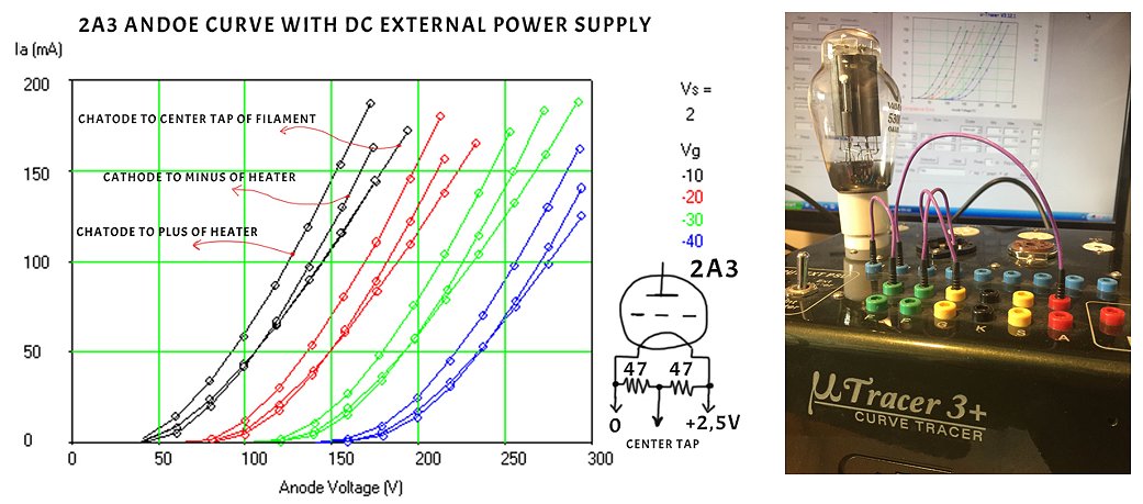
I am working on a 2A3. I use a DC external power supply.
Because I know that the measurement is a function of the point where the cathode is connected to the filament I make three tests.
To my surprise there is the big difference between the three tests:
1) Cathode connect to minus of heater
2) Cathode connect to + 2,5 volt of the filament
3) Cathode connect to central point of the filament ( I use a 47 + 47 ohm in series to the filament).
Now I ask you, because there is big difference what is the right curve?
The answer is that all curves are right!!
Which curve you use, depends on the circuit the tube is used in.
In the circuit you choose which point is the reference for the grid voltage.
It can be heater terminal 1 or heater terminal 2 or some point in between.
You select the curve that corresponds to the circuit topography that you use.
How can I test/trace diodes and rectifier tubes with the uTracer?
I did a small writeup in this topic on my Lab Notebook page. Have a look here
| previous page | back to first page |