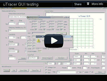


GUI v3p10 , GUI v3p10 exe only , GUI v3p8 , GUI v3p8 exe only , GUI v3p7 , GUI v3p6.

The GUI makes use of a number of objects which reside in additional .ocx files. Examples of these object are the serial communication object which resides in “mscomm32.ocx,” the progress bar used to indicate the status of the heater which resides in “MSCOMCTL.OCX” and the Common Dialog Forms that are e.g. used to browse for a file which reside in “comdlg32.ocx.” On a computer which has Visual Basic 6 installed, these components are usually present. However, if the program is distributed to other computers these files, together with some .dll files need to be installed.
Fortunately the Visual Basic Package includes the “Package & Deployment Wizard,” which automatically installs these components when they are missing. The “Package & Deployment Wizard,” first analyzes the project to see which components and additional files are required. It then generates a “Cabinet” (.cab) file which basically is a zip file which includes the program executable as well as all the other files. A setup application unpacks the compressed file and copies the .ocx and .dll to the system folders and registers the files in the registry file.
Installing the V3.5 Graphical User Interface.
Installing the GUI is straightforward:
- If your computer does not have a native COM port you will need to have a USB to serial adapter. If you buy one make sure it uses an FTDI chipset (see remarks at the end of this section). Before installing the GUI I recommend to install the USB -> Serial adapter driver first. Make sure that the communication protocol is set to: 9600 baud, 1 stop bit, no parity check. Make sure that you know to what COM port number the adapter is assigned.
- Download the zip file to a directory.
- Unzip the zip file.
- Double-click setup.
- Follow the instructions of the setup program.
- Start the uTracer GUI from your program list
I tested the installation of the GUI on my “overfull” XP laptop, as well as on the almost “virgin” Windows 7 laptop of my son (top picture). In both case the installation proceeded without a problem. There was however a problem with the USB to Serial converter on the Windows 7 platform. When
 the GUI tried to read the COM port, the program crashed with a “Run time error 8020, Error reading comm device.” A search on internet revealed that this particular problem only occurres for USB to serial converters based on the “Prolific” chipset, and only under Windows Vista or Windows 7. Indeed I used a Sweex adapter based on the Prolific chip set. Fortunately, when I tried a Digitus DA-70156 USB to Serial adapter with an FTDI chip set it worked flawlessly.
 If you consider building your own uTracer I strongly recommend to download the GUI and test first it. It is very easy to test the GUI and the communication of the GUI with the (emulated)
COM port, without having the actual uTracer hardware connected. Although
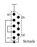
it is possible to test the GUI with the COM port just open, a more thorough check is possible if the COM port is fooled by connecting the transmit pin to the receive pin. The small dummy uTracer circuit on the right shows how such a circuit can be wired on a 9-pin female RS232 (DB9) connector. Pins 2 and 3 are the data pins. The other wiring makes sure that the handshake signals are properly bypassed.
To test the GUI, first install it as described above. To have a 100% fail safe test, connect the “dummy uTracer” circuit to the COM port. Start the uTracer and click the “Debug” command button. Select the proper COM port number and press the “Ping” command button. Pressing the Ping button will cause the GUI to send two command strings to the uTracer. The first string is a <00> “start measurement sequence” command, and the second string is a <50> “read out all analog channels” command. When the COM port is open, the GUI will transmit the first character “0” and then wait for uTracer to echo this character. Since nothing is echoed it will detect a timeout and after 2 seconds and give a timeout error. When the dummy circuit is connected to the COM port, the GUI will successfully transmit the two command sequences and then after 10 seconds give a timeout error because it expects a result string to be send back by the uTracer. Both responses indicate that the GUI and the communication with the COM port function properly.
Thanks!

| previous page | next page |