
The uTracers are small and affordable tube testers - or better tube curve tracers - that measure all the important tube parameters and tube curves in exactly the same way as they can be found in data sheets. It is the ideal instrument if you want to design your own tube circuits, check the quality of a tube, or if you are simply a collector of tubes (like me) and just want to bring those vintage wonders of technology back to life!
The uTracer circuit generates all the voltages needed to power up a tube under realistic conditions, while it measures the currents. To keep the circuit as small as possible, the user interface is taken care of by an elaborate Graphical User Interface (GUI) running on your laptop or desktop. With the GUI it is possible to set-up a measurement, and to display and manipulate the measurement data so that it is represented in the same sets of curves as in the datasheets.
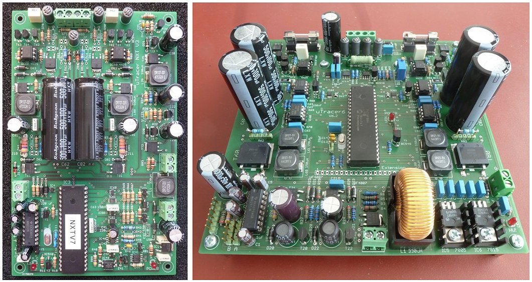
The two uTracer circuits that are currently available.
Left: the uTracerNXT that has replaced the well known uTracer3+. Right: the uTracer6
The circuit is kept small by using state-of-the-art components and circuit concepts. By using a pulsed measurement principle, “heavy” and expensive transformers, heat-sinks and fans are eliminated, making the uTracer one of the cheapest and also the smallest tube testers / tube curve-tracers around.
To keep costs at a minimum, the uTracers come as a construction kit complete with a PCB with the “difficult” surface mounted components already installed and an comprehensive printed and bound step-by-step construction manual. When the board is fully populated, tested and calibrated, it can serve as the heart of your dream tube tester/tracer. The constructions manuals can also be downloaded and previewed by clicking on the Downloads tab on the top of this page.
There are currently two uTracers available. The very new uTracerNXT is the successor of the very popular uTracer3+ of which more than 2300 units have found their way to tube enthusiasts. Like the uTracer3+, the uTracerNXT targets regular low and medium power (audio) tubes. The maximum voltages for the uTracerNXT are 500 V for anode and screen and -120 V for the control grid. The somewhat older uTracer6 specifically targets medium to high power audio and transmitter tubes with maximum voltages up to 1000 V. Especially for transmitter tubes an extension board (shield in modern terminology) is available that extends the grid bias range to also include positive voltages resulting in a -100 V to +100 V range. More detailed information on the specifications of the two uTracers can be found here.
No attempt has been made to design or supply a completely “ready to use” product including tube sockets etc. since has experience learned that most tube enthusiasts have very specific ideas about how their tubes tester should look like. Some embodiments are very simple and straightforward, while others have used the uTracer to create elaborate instruments. Please click on the Testimonials tab on the top of this page to browse through the many beautiful creations people have come up with.
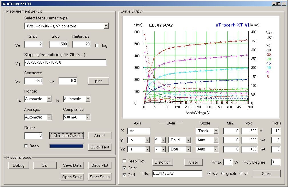
The control panel of the uTracer, the Graphical User Interface (GUI). In this figure the Ia/Is-Va curves were measured for an EL34 (6CA7).
A typical uTracer system consists of four components:
-
The uTracer hardware
A PCB (view sizes here) containing all the electronics, boost converters and a programmed PIC microcontroller which controls everything and communicates with the PC. Since integrating a native USB interface in a semiprofessional project like this is very complicated, the uTracers communicate with your PC via the good old RS232 serial interface. If you do not have a RS232 to USB converter lying around, you will need to purchase one. They are very cheap, but make sure you buy a true RS232 compatible device! -
A Graphical User Interface (GUI)
The “default” GUI as it can download from the website is used to set measurement characteristics like type of measurement, voltages and current ranges etc. You can chose to measure and plot typical tube characteristics, or perform a so called “quicktest” which measures a range of tube parameters in a single bias point (see impressions below). The default GUI is written in VisualBasic 6 and only directly usable on Windows operating systems. However, Ihor Small has developed an alternative GUI written in JavaScript the so called “uTracerJS.” The uTracerJS GUI runs from your browser and is therefore completely operating system independent! I fully endorse the uTracerJS which supports all three uTracers and offers all the features of the standard GUI. You can download the uTracerJS from Ihor’s website. -
An (old) laptop power supply
The uTracers require an 18-20 V power supply, capable of supplying at least 1.5 A current. An old 19.5 V laptop power supply is perfectly suitable for this. Most people will have an old laptop power supply lying around and otherwise it shouldn’t be too difficult to find one second hand on fly markets etc., and of course you can buy a new one or purchase an alternative suitable power supply. -
A tube socket arrangement of some sort
This is really the part where you can really go wild and use your creativity, fantasy and imagination to create a tube tester specifically to your needs. If you go to the testimonial pages under the tab Testimonials you will find hundreds of creations by proud uTracer owners, ranging from very basic ones with only one or two tubes sockets hardwired to directly test the tubes of their amplifier, to very elaborate systems using rotary switches or even relays matrices to connect the uTracer to a wide variety of tubes.
The uTracer project and development started way back in 2010 with the publication of the project in a “project-blog.” This generated a lot of response and enthusiasm from people all over the world. Many people asked me to make a kit out of this project. And here we are now in 2026 with more than 3000 (!) uTracers sold in 96 countries! Read more about the history of the project, the ups and downs during the development of new uTracer generations on the Project History page.
Finding your way around this website
The content on this website has grown rather organically so I can imagine that sometimes it can be a tricky to find the information you are looking for.
So here a small guide to the tabs on the top of this page:
-
Introduction
The pages under this tab are meant to give a quick overview of the uTracer concept, the working principle, and its use. Most explanation will be done using the new uTracerNXT as an example, although I will also use results and examples of the older uTracers 3 and 6. Under sub-tab Project History you will not only find a small project history, but also a list of the uTracer versions I have worked on over the years, of which only a few made it into a real kit. An enthusiastic group of people has and still is contributing to extend the functionality of the uTracer family. You can find examples of this under sub-tabs Spice Modeling and Load line tool. -
Testimonials
Already since the beginning of the uTracer adventure I have encouraged people to share their experiences and send me a few pictures of the tubes tester they created around the uTracer. Although the uTracer3 is no longer available, I encourage you to have a look at the hundreds of beautiful embodiments people have come up with! -
Order
All the information you need to order a uTracer. Ordering a uTracer is a two-step procedure. You mail me first at Ronald@dos4ever.com so that we can first discuss technical related issues (if any). I then bring you into contact with my wife who is handling all practical stuff like finances, administration and shipment. -
Downloads
Here you can download the GUI’s for the different uTracer versions as well as the latest version of the construction manuals. Also available is a User Manual. The currently available manual is specifically written for the uTracer3. However, 95% of the information in the manual also directly applies to the uTracer6 and uTracerNXT. Adapting the manual for the uTracerNXT is on my to-do list. -
All Weblogs
I like to use the weblog format to document the development process of the different uTracer projects. The weblogs force me to properly write the thought process behind the development. They are therefore primarily intended for my own documentation, but I know many people find them interesting to read. On the Project History page you can find a table listing all the different uTracer versions including a link to the corresponding weblogs.
Of special interest if the Lab Notebook page which discusses ideas and concepts that one way or the other do not fit in the regular weblog pages. Many of them relate specifically relate to the now obsolete uTracer3, but some of them are also of interest to users of the utracer6 and uTracerNXT such as: -
Frequently Asked Questions (FAQ)
A list with some of the questions I regularly get, including my answers. Currently the questions are still very much focussed on the uTracer3. Re-organizing and updating of this page is also very much on my to-do list, but nevertheless, the page contains very useful information.
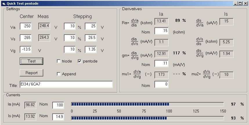
Apart from the full curves it is also possible to quickly measure the most important tube parameters in a specific bias point.
In this example an EL34 / 6CA7 is measured in its nominal bias point
The series of videos below give an impression of how the uTracer operates. The videos are a bit outdated because they show an old version of the GUI, while in the newest version many new features have been added. The basic operation and layout of the GUI has however remained the same.
| |
|
|
|
|
|
|
|
Click on one of the images for a guided tour through the new GUI!

| previous page | next page |