|
|
|
An E1T clock The making of the E1T |
|
The E1T tube you see on the left has been "in the family" for as long as
I can remember. Probably my father took it home from work (he worked at the
Shell laboratory in Rotterdam) or he bought it in one of the surplus shops
in Rotterdam my father and I used to visit every Saturday morning when
I was a child.
 Because it was such a strange and funny looking
tube we always used to play with it. Being under the assumption
that the tube was broken, I was never particularly careful with it, nor did
I make any attempt to bring the tube to life.
Because it was such a strange and funny looking
tube we always used to play with it. Being under the assumption
that the tube was broken, I was never particularly careful with it, nor did
I make any attempt to bring the tube to life.
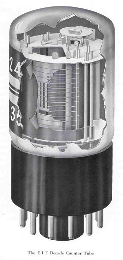
From the commonly available datasheet, I knew that this was not just a display device, but that the tube actually counts pulses and additionally displays the sum. This implies that the tube has a memory of the equivalent of 3.5 bits! On top of that, the tube even has a provision to generate a carry for the next digit. How did they do it? I work at the central Philips Research Laboratory in Eindhoven, Holland. Obviously, the Lab keeps a complete archive of all research reports and papers. Browsing through some old volumes of the Philips Technical Review in the library, I happened to stumble across a paper, which described the E1T tube in great detail [1]. It is one word beautiful! The whole paper reads like a poem, it is so elegant and ingenious; undoubtedly one of the masterpieces of vacuum tube engineering.
 Unfortunately there does not appear to be a fancy and concise name for
the tube. Dieter categorizes the tube as a "beam Deflection Decade Counter Tube" [2].
I would have liked to believe Joris Roehrenbude who categorizes the E1T as a
Trochotron [3]. It sounds a hell of a lot more interesting than
a "Decade Counter Tube". Unfortunately on further investigation it appears
that a Trochotron is really something completely different [4].
Philips itself finally adopted the name "Decade Scaler Tube" [5]:
Unfortunately there does not appear to be a fancy and concise name for
the tube. Dieter categorizes the tube as a "beam Deflection Decade Counter Tube" [2].
I would have liked to believe Joris Roehrenbude who categorizes the E1T as a
Trochotron [3]. It sounds a hell of a lot more interesting than
a "Decade Counter Tube". Unfortunately on further investigation it appears
that a Trochotron is really something completely different [4].
Philips itself finally adopted the name "Decade Scaler Tube" [5]:
"The E1T, previously referred to as a "counter tube", is now termed a "Scaler
Tube" to preclude confusion with counter tubes such as Geiger-Muller tubes etc."
You will appreciate that I feel an emotional and moral obligation to follow
that convention.
Digging in the lab's archives I found two additional "Internal Research Reports" related to the E1T. The first report dates from February 1949 [6]. It is a short 3 page memo with some measurement results on 6 sample tubes, which had been prepared by the "proefafdeling" (sample department?). The tubes worked apparently as expected. It was emphasized that exchanging a tube for another tube did not require any adjustment of the biasing components. Apparently it was feared that the biasing of the tubes would be extremely critical. The second report is from September 1949 [7]. It was an interim report marking the transfer of the tube from research to the "radiobuizenlab" (radio tube laboratory). The nine page report shortly points out the critical construction aspects of the tube and how they relate to the performance. The efficiency of the report is striking. So already early in 1949 working research samples of the E1T were available! The first external publication probably marking the introduction of the E1T on the market I could find is from 1952 [8], it is the Dutch version of [1] published half a year earlier.
Surfing the web I bought a second E1T from Mattijs de Vries [9]. Mattijs really offers excellent and prompt service and I can not recommend him too highly. When it appeared that there was a defect in a socket I bought from him, my money was refunded the same day without questions asked. Having a second tube, I set about trying to bring the tube back to life. It appeared that even the first tube that I had all along was fully functional, and it was very rewarding to see the filament glow-up for the first time in perhaps forty years.
At this point I would like to make an appeal: If you have one or more
E1T tubes lying around, and if you do not have any use for them, you can
make a clock addict very happy, send me an e-mail. You will find my
e-mail address at the bottom of my homepage.
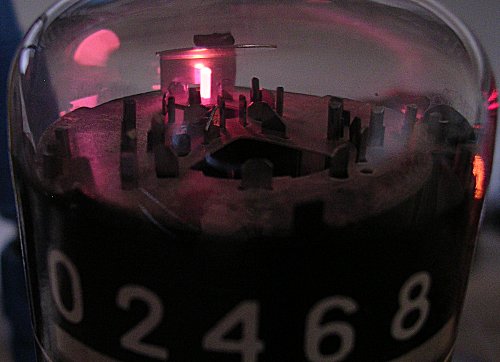
Figure 1. The waking of the sleeping beauty. The filament glowing after forty years of sleep as if nothing happened.
| to top of page | an E1T clock | The making of the E1T | back to homepage |
In this section you find an edited version of the original description of the
E1T counter tube from the "Philips Technical Review" [1].
The full pdf version of the document is unfortunately too heavy for my web-page
(3M). On request (see e-mail address homepage), I will be happy to mail it to you.
The figure numbers in this section refer to the picture numbers of the scanned
images.
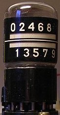
At given values of deflection, the beam passes through one of the ten
vertical slots in the slotted electrode (g4), which is at a positive
voltage. It will be shown later how a special circuit ensures that the
beam can occupy only one of these ten positions. Some of the electrons
passing through a slot impinge on the anode (a2) placed behind the slotted
electrode; the remainder pass through an aperture in this anode and
impinge on the envelope. The part of the envelope situated behind the
anode is lined with fluorescent material, so that a fluorescing mark is
produced behind the opening in the anode through which the electrons pass.
The number opposite this mark thus indicates the position of the beam.
When the beam passes through slot 9, it has not reached its extreme
position, but can be deflected slightly further under the influence of a
following pulse. When this occurs, it impinges on the so called reset
anode (a1). Before discussing this, it will be shown how the beam is
fixed at well defined positions.
Fig. 4a gives a schematic representation of an imaginary cathode-ray tube,
containing an electron gun, a set of deflection electrodes and an anode.
When the potential vD of one of the one deflection electrode is kept
constant and the potential vD' of the other is varied, the electron beam
will move along the anode, but the anode current ia remains constant (line
I in fig. 4b). When the deflection electrode D' is connected to the anode
and these two electrodes are fed via a common resistor Ra from a battery
with voltage Vb (fig. 4c), the following equation, however, applies:
va2 = vD' = Vb - ia*Ra. This relation is represented by the line II in
Fig. 4b. The point of intersection P of the lines I and II gives the state
of equilibrium; the electrode D' then assumes a potential which
corresponds to the abscissa of P, and according to this given potential
the beam occupies a well-defined position.
How the characteristic ia2=f(vD',a2) is obtained
When the beam is now made to move from slot 0 to slot 9 by (continuously)
lowering the voltage vD',a2 it might be expected at first sight that a
characteristic ia=f(vD',a2) as shown by curve I of fig. 7b is obtained:
each time the beam is redirected on a slot, ia2 reaches a maximum (which
is the value for all slots), and each time the beam points to the centre
between the slots, ia2 drops back to zero.
Assuming for the time being
that the characteristic had this form, it would be possible to proceed
according to fig. 5, and to give VB and Ra2 such values that the line II,
which represents eq.(1) graphically, intersects all waves of I (fig. 7b).
In practice, however, with a slotted electrode according to fig. 7a, the
characteristic ia=f(vD',a2) will not assume the form I of fig.7b, but that
of 7c. This is caused by a defocusing of the beam as it is displaced
further to the left due to the asymmetry in deflection (vD constant and
vD' variable). The disadvantages of the latter form are that the magnitude
of Ra2 (slope of line II) must remain within very narrow limits.
In order to obtain the much more favorable characteristic I of fig. 6,
the slotted electrode has been provided with additional apertures, which are
also scanned by the beam, so that an additional current is passed which
increases as the beam proceeds further to the left. The most obvious solution
is to make a triangular aperture in the slotted electrode (O in fig. 8). It
would nevertheless be very difficult to obtain the desired improvement in
this way. This is mainly due to the presence of the suppressor grid (g3)
in front of the slotted electrode. For this reason the idea of a narrow
triangular aperture was abandoned in favor of rectangular apertures whose
positions with respect to the grid wires are less critical.
Mechanism of the displacement of the beam from 0 to 9
The positive-going pulses to be counted are applied to the left deflection
electrode D via a blocking capacitor. In order to understand how the beam is
shifted to a following position at each pulse, it should be recognized that
the characteristic I shown in fig. 6 is applicable to a constant voltage vD at
the left deflection electrode, and that the angle of deflection is a
function of vD'-vD. An increase of vD by an amount Vi therefore corresponds
to the line I being shifted to the right over a distance corresponding
to Vi (fig. 13).
In practice, however, the stray capacitance to earth of the electrodes a2
and D' and their wiring, represented by Ca2 in fig. 5, is shunted across
Ra2 and impedes sudden changes of the potential of a2 and D'. Provided the
condition is satisfied that the leading edge of the pulse is sufficiently
steep, the potential vD',a2 may be considered constant during the rise time
of the pulse. This amounts to the line I of fig. 13 being shifted to the
right (I') over a distance equal to the amplitude Vi of the pulse, the anode
current thus assumes the value A1A. This differs from the original value;
the difference is supplied by the capacitance Ca2.
Provided that the second condition is also satisfied, namely that the decay
time during which the input pulse decays from Vi to zero, is sufficiently
long, the characteristic I' will gradually return to I, and A will be shifted
to the adjacent stable point of intersection between I and II, i.e. point 1.
In order to ensure that the beam is shifted just one step to the left,
a third condition must be imposed to the beam, namely that the amplitude
Vi should be roughly equal to the voltage difference Ve which corresponds
to the horizontal difference between two adjacent stable points of
intersection and amounts to approximately 14 V; it will be clear that at too
small an amplitude the beam will return to its original position, whereas
at too large an amplitude it will advance two or more positions.
 Fig. 3a shows a cross-section of the decade counter tube, whilst fig. 3b
shows the diagramic representation which will be used in circuit
diagrams. The cathode is of the conventional type as used in receiving
valves, apart from the fact that it emits electrons from on side only of
its rectangular cross-section. A control grid (g1), four rod-shaped
focussing electrodes (p1, p2) and an accelerating electrode (g2), together
with the cathode, form the electron gun. This has been so designed that
the cross-section of the electron bean thus obtained is not circular but
ribbon-shaped. A ribbon-shaped electron beam has the following advantages:
Fig. 3a shows a cross-section of the decade counter tube, whilst fig. 3b
shows the diagramic representation which will be used in circuit
diagrams. The cathode is of the conventional type as used in receiving
valves, apart from the fact that it emits electrons from on side only of
its rectangular cross-section. A control grid (g1), four rod-shaped
focussing electrodes (p1, p2) and an accelerating electrode (g2), together
with the cathode, form the electron gun. This has been so designed that
the cross-section of the electron bean thus obtained is not circular but
ribbon-shaped. A ribbon-shaped electron beam has the following advantages:
The ribbon-shaped beam thus obtained proceeds between two deflection
electrodes (D, D', fig. 3). These have been so positioned that the beam
almost touches one of these electrodes in each of it's extreme positions,
deflection sensitivity thus being at a maximum.
Step-wise deflection of the beam
 Advantage is taken of this principle for fixing the position of the beam
in the counter tube. In this case too, the anode a2 and the deflection
electrode D' (i.e. the one nearest to the figure 0) are connected to
direct voltage source Vb via a common resistor Ra2 (fig. 5); the potential
of D and a2 is denoted by vDa2. The straight line I of fig. 4b is now,
however, replaced by the undulated curve I of fig. 6; the way this curve
is obtained will be shown presently. This curve is intersected 19 times by
the resistance line II. Each of these points of intersection corresponds
to a condition of equilibrium - although only ten points of intersection
numbered from 0 to 9 represent stable positions. From this it may be seen
that the position of the beam indicated diagrammatically in fig. 3a is one
of its stable positions, i.e., passing partly through a slot and impinging
partly on the metal on the left of this slot: in fact, when the beam is
deflected further to the left the current initially increases, in
accordance with characteristic I near the points of intersection 0...9
(fig. 6).
Advantage is taken of this principle for fixing the position of the beam
in the counter tube. In this case too, the anode a2 and the deflection
electrode D' (i.e. the one nearest to the figure 0) are connected to
direct voltage source Vb via a common resistor Ra2 (fig. 5); the potential
of D and a2 is denoted by vDa2. The straight line I of fig. 4b is now,
however, replaced by the undulated curve I of fig. 6; the way this curve
is obtained will be shown presently. This curve is intersected 19 times by
the resistance line II. Each of these points of intersection corresponds
to a condition of equilibrium - although only ten points of intersection
numbered from 0 to 9 represent stable positions. From this it may be seen
that the position of the beam indicated diagrammatically in fig. 3a is one
of its stable positions, i.e., passing partly through a slot and impinging
partly on the metal on the left of this slot: in fact, when the beam is
deflected further to the left the current initially increases, in
accordance with characteristic I near the points of intersection 0...9
(fig. 6).
 In fig. 7a a slotted electrode and an anode have been drawn as flat
planes. It is assumed that the ten slots have the same dimensions and are
equidistant and that the thickness of the ribbon-shaped beam exceeds the
width of the slots and is less than the width of the spaces between the slots.
In fig. 7a a slotted electrode and an anode have been drawn as flat
planes. It is assumed that the ten slots have the same dimensions and are
equidistant and that the thickness of the ribbon-shaped beam exceeds the
width of the slots and is less than the width of the spaces between the slots.
 As a starting point it is assumed that the beam occupies one of its stable
positions, for example position 0. If a positive pulse is now applied to
the left deflection electrode, so that vD is temporarily increased, the
beam will tend to move to the left (fig. 3a); the number of electrons
passing through slot 0 decreases, i.e. the anode current ia2 is reduced. If
no stray capacitances were present, the decrease of ia2 would result
in a rise of the potential of the anode and of the right deflection electrode
connected to it, and this increase of vD',a2 would counteract the deflection
to the left, so that the beam would be retained at position 0.
As a starting point it is assumed that the beam occupies one of its stable
positions, for example position 0. If a positive pulse is now applied to
the left deflection electrode, so that vD is temporarily increased, the
beam will tend to move to the left (fig. 3a); the number of electrons
passing through slot 0 decreases, i.e. the anode current ia2 is reduced. If
no stray capacitances were present, the decrease of ia2 would result
in a rise of the potential of the anode and of the right deflection electrode
connected to it, and this increase of vD',a2 would counteract the deflection
to the left, so that the beam would be retained at position 0.
| to top of page | an E1T clock | The making of the E1T | back to homepage |
Before starting the description of the tester, it should be stressed that the
voltages used in this circuit are lethal! Never touch any part of the circuit
while the high tension supply is on.
Figure xx depicts the circuit diagram of the tester.
The circuit consists of three different parts:
1. The E1T valve with biasing circuit, 2. a pulse generator and pulse shaping
circuit, 3. the reset circuit.
Figure 2. Circuit diagram of the E1T tester.
The upper part of Fig. 2 forms biasing
circuit. It is directly copied from the E1T datasheet. The voltage
devider around R14, R15 and R16 provides the biasing voltages for the "input"
deflection plate D (156 V) and the control grid g1 (12 V). Any transients
on these voltages are removed by decoupling capacitors C9 and C8.
 The current
through the voltage divider is ca. 2 mA. This is enough for the low-current LED
D1 to indicate that the high voltage supply is on. The total energy dissipated
in the divider is ca. 0.6 W, a bit too high for standard 1/4 resistors. One watt
resistors would do, but I only had two watt resistors. Although the tube is designed
for a 6.3 V filament voltage, I use 4 V just not stress these old beauties too much.
The most crucial resistor
in this part of the circuit is R21. This 1M resistor links the anode current
and the deflection plate voltage. The datasheet is very fussy about the tolerances
of the resistors, especially of the 1M anode resistor which is specified at 1%.
If you are not interested in pushing the tube to it's counting speed limits
5% resistors will also work well. In my circuit the maximum counting speed was about
1 kHz.
The current
through the voltage divider is ca. 2 mA. This is enough for the low-current LED
D1 to indicate that the high voltage supply is on. The total energy dissipated
in the divider is ca. 0.6 W, a bit too high for standard 1/4 resistors. One watt
resistors would do, but I only had two watt resistors. Although the tube is designed
for a 6.3 V filament voltage, I use 4 V just not stress these old beauties too much.
The most crucial resistor
in this part of the circuit is R21. This 1M resistor links the anode current
and the deflection plate voltage. The datasheet is very fussy about the tolerances
of the resistors, especially of the 1M anode resistor which is specified at 1%.
If you are not interested in pushing the tube to it's counting speed limits
5% resistors will also work well. In my circuit the maximum counting speed was about
1 kHz.
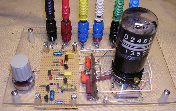
Figure 3. Front side view of the E1T tester.
The pulse generator and reset circuit were designed only using npn and pnp transistors. The primary reason was that I thought these would be more "rugged" than ICs in such an high voltage environment. Additionally I wanted to show that for these simple functions there are still simple alternatives for the relatively complex (and boring) integrated standard solutions. The additional advantage is that the circuit works over a wide supply voltage range. The heart of the oscillator is the multivibrator around T2 and T3. At "non-inverting" output, the collector of T3, we find 330 µs pulses (determined by C2 and R6) separated by a much longer variable length pause (determined by C1, R4 and R5). By adjusting R5 the repetition frequency is adjusted between 0.5 and 200 Hz.
As explained in the previous section,
the rising edge of the input pulse to the E1T should be steep enough so that
the voltage at the node of anode a2 and deflection plate D' can be considered
constant. The datasheet specifies a leading edge of at least 20 V/µs.
On the other hand the slope of the trailing edge should not exceed
1.2 V/µ second so that the potential vD', a2 can follow the trailing
edge. Both conditions are met by using an active pull up by means of
transistor T1 and resistor R1 for a passive pull down. The base of T1 is
connected to the "inverting" output of the multivibrator. This output is
normally high, and is low during the 330 µs pulses. During the low time
T1 is switched on and driven hard into saturation. The trailing edge of the
pulse is determined by C5 and R1.
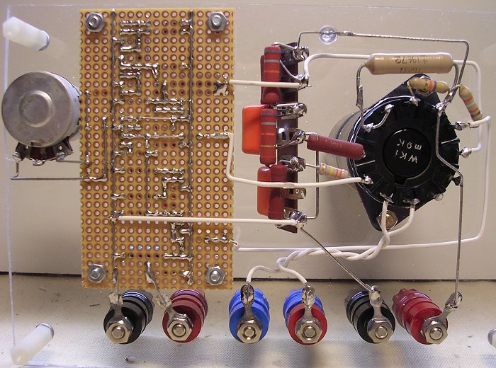
Figure 4, a rear view of the tester.
When a new input pulse is given when the tube is already in the ninth
position, the electron beam advances to the left again an now impinges
on anode a1. This anode is connected to the 300 V supply via resistor R18.
The anode current now flowing through R18 will cause a negative trailing
edge at a1. After removal of the DC component by blocking capacitor C6, this
pulse is used to trigger the one-shot pulse generator formed by T4 and T5.
It appeared that also during normal counting from 0 to 9 small pulses where
induced at the anode a1. Capacitor C3 is used to filter these pulses so that
they do not cause unwanted resets. The one-shot produces on the collector
of T5 a positive going pulse of 2.2 ms. This pulse will switch on T6 which
in turn will cause a negative pulse of -15 V on the control grid g1. This
negative pulse will cut-off the electron current in the E1T. As a result
the potential on anode a2 and deflection plate D' will return to 300 V
again. When the valve is turned on the beam is in the right position again,
in other words being reset to zero. Isn't it beautiful !?
Figure 5. The working of the transistor one-shot multivibrator: A. rest
position, B. potentials in rest position,
C. situation during pulse.
Although most people are fairly familiar with the transistor multivibrator
circuit, the one-shot circuit is less know. Its working is easy to
understand. In Fig. 5A the npn version of the one-shot circuit is depicted.
Lets for the moment assume that the one-shot is in its stable rest
position. The capacitor will be charged then, so that we may think it
removed from the circuit (Fig. 5B). In this situation the base of T2
is pulled high by R2 so T2 is conducting. As a result the collector of
T2 will be low so that T1 is not conducting so that it's collector
will be high. When in this situation
a positive pulse is applied to the base T1, T1 will start to conduct,
pulling it's collector low. Since the capacitor was charged to 15V as indicated
in fig. 5A, the base of T2 will initially be pulled down to -15V,
assuming that the emitter-base junction of T2 does not break down (Fig. 5C).
This situation continues until the capacitor is charged so far that T2 starts
to conduct again. The one-shot is now back in its rest position.
| to top of page | an E1T clock | The making of the E1T | back to homepage |
The tube worked directly without any adjustments. At a filament voltage of 4 V
it takes about 30 seconds for the filament to warm up. I did not make any
special attempts to push the tube to its speed limits. The rather lengthy
reset pulse limits the counting speed to ca. 1 kHz. Although designed for
a HT supply of +300V, the circuit of Fig. 2 works fine for voltages
as low as 200V.
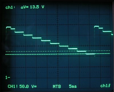
Figure 6. Anode a2 = deflection plate D', voltage while stepping from 0 to 9.
The scale is 50 V per division, 1- indicates 0 V.
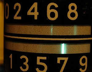
Figure 7. Defocussing of the beam when it is deflected further to the left.
All in all the tube was quite easy to handle. I would love to make a clock
out of them, but unfortunately I have "only" two tubes. For a clock I would
not make use of the carry anode a1. I think it would be simpler to drive
the pulse and reset inputs of every individual tube directly by a
micro-controller. This would only require an additional +15V supply and a few
simple driver circuits. For the input pulse driver the simple circuit
consisting of T1,T2,R1,R2,R3 and C5 would do. For the reset pulse driver
T6,R12,R13 and C7 would do. Driving each tube individually would enable some
nice visual effects, e.g. a "slot machine" kind of spinning of every digit
for every new minute. I personally would not leave a clock with such rare
tubes on all the time. I would use one of these simple and low-cost motion
detectors that you may also find in garden lights etc.. to switch the clock
on only when somebody is in the room for a longer period of time.
After reading this page, Vincent Crabtree remarked that the most stressful time
for the heater is the moment when the coil is cold and power is applied. He suggested
to implement a soft start heater PSU or a constant current source to gently
heat the fillament. Thank you Vincent !
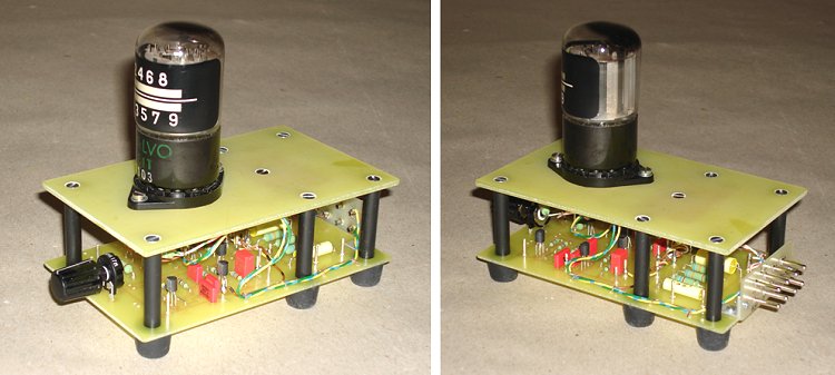
Figure 8. The E1T Tester as built by Dusan from Germany.
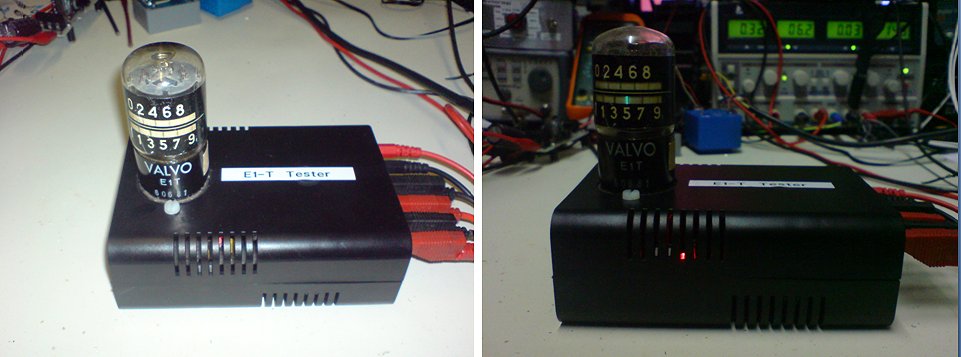
Figure 9. The E1T Tester built by Roger Leifert from Germany.
| to top of page | an E1T clock | The making of the E1T | back to homepage |
| to top of page | an E1T clock | The making of the E1T | back to homepage |
"Oh, Sorry", Radio Bulletin, no. 7, 1955