Both my parents were from the generation who thought Fluorescent Lighting was the best thing to flood every room in the house with light. Especially my father would, if he could have his way, lighted every room in the house with Fluorescent Light Tubes. My whole life the kitchen in the house of my parents was illuminated by two 40 Watt Fluorescent Light Tubes which would literally flood the kitchen in a wealth of bright white light. It was not until after I met my wife that I learned that most people prefer a more “romantic” light setting, even in the kitchen!
Be that as it may, at a certain moment even my father thought it was a bit ridiculous to have 80 Watts of light burning in an empty kitchen the whole evening. I even remember even one of our neighbors asking if electricity for was free in our household. Fond as my father was of especially the small 8 Watt Fluorescent Light Tubes (we had one in the hall, the first floor landing, and my parents even had one as a bed-light), he was playing around with the idea to add a small 8 Watt tube next to the two massive 40 Watt tubes. The problem was that he couldn’t come up with an elegant solution of how to switch from one lamp to the other. The mains wiring in the house was ancient, and we were afraid that even looking at the old cotton-wire isolated (!) wiring would cause short-circuits, so adding an additional wire was out of the question. Mounting a switch in the lamp housing on the ceiling with a cord or something like that hanging from the lamp in the middle of the kitchen was also absolutely vetoed by mother.
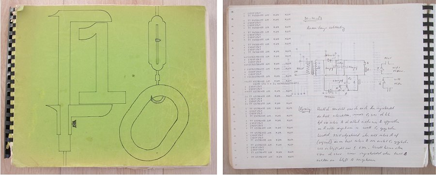
Figure 1. My notebook and the relevant page dated 10th October 1983. Click here for a larger version.
At that time I was in my second year at university, and although during the week I lived in chambers in Eindhoven, I used to visit my parents every weekend. One Sunday, when my father raised the problem of the kitchen light switch again, I had the idea to use a “quick double click” on the original light switch to turn the main light off, and the small light on. The solution was actually quite elegant: the main light would switch on and off as usual, only when the main light was already on, a short click with the light switch would turn the 80 W light off and the 8 W light on.
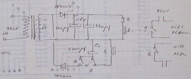
Figure 2. Circuit diagram of the “Two-Lamp-over-one-Wire” Circuit.
The circuit was designed and tested - if I remember correctly - within an hour or so. In those days I used to keep a notebook for circuit diagrams that I had made from a pile of almost empty sheets of paper I had found near one of the huge line-printers we had in the computer-center at the university. A few months ago, the final departure from this nice circuit which served us so well over many years (see end of this page) was the occasion to see if I could still find the original entry on the circuit in the notebook. And there it still was, it was even signed 30 October 1983, a Sunday (I checked it).
Figure 2 shows the circuit diagram of the light switch. No micro-controller, no ICs, not even a transistor. Just a small transformer and two relais. The relais I used actuate at ca. 4-6 V and have 4 change-over contacts capable of switching 220 V. Capacitor C1 was selected high enough so that the relais didn’t produce a 50 Hz hum, and low enough so that when the mains power was removed the relais would be released in a fraction of a second. Capacitor C2 was selected so that when fully charged, it can hold the relais for about 3 seconds. The working of the circuit is quite tricky, and is best explained by the three diagrams below which show the circuit and the position of the relais contacts during the three phases of operation.
|
When light switch S is switched on for the first time, both capacitors are dischared. In this state relais A will actuate. In the diagram on the left the contacts of relais A have been drawn in the new position. With relais A actuated the 80 W light will be switched on. At the same time C2 will be charged through D2. |
|
When light switch S is briefly opened, relais A will be quickly released because the capacitance of C1 is selected such that it will only hold relais A for a fraction of a second. As soon as relais A is released however, relais B will be actuated through switch S2A. The value of capacitor C2 is such that it will be able to hold relais B for several seconds. Note that the polarity of D2 is such that C2 will only discharge though relais B. |
|
When light switch S is closed again before C2 has been discharged and relais B is released, relais B will remain actuated because switch S5B is closed. Relais A will remain released because S4B is open. With relais B actuated the 8 W light will be on. When finally light switch S is opened for several seconds, long enough to discharge S2 to such a level that relais B will be released, the circuit is back in its starting condition again. This fact is clearly audible by a soft click. |
So why spend a whole page on such an almost trivial circuit? Well, the reason is that it is rather special to me personally. The period we are talking about here was for the family a difficult time. My father had never been a very “easy” man, but since his retirement he became a very difficult man who made life hell for my mother and consequently also for us children. But the work on this circuit, which was conceived, built and installed all on that very same Sunday, all went – as I recall it – in perfect harmony! It has served the family ever since without a single flaw.
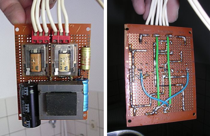
Figure 3. Although it doesn’t look like much. The PCB was reliable enough to serve us for 25 years.
In 2000 my father died, and a few years later - in 2004 - my mother moved to a small apartment for senior people in the village of Valkenswaard where I live. The move was for my mother the ideal occasion to break with almost all the ties with a difficult past. She threw away almost all the old furniture and bought new ones, exactly the way she wanted it (IKEA of course). But the kitchen lamp including the switch circuit was one of the things she took along being so used to it that she could not part with.
I personally think that the few peaceful years my mother had, living near us and the children, certainly belonged to one of the happier periods in her life. However, after a few years it became clear that she was suffering from dementia. For a long time she was still able, with the help of us, to get on with her life, but last year that came to an abrupt end. In April 2009, I was diagnosed with cancer, and in exactly the same period my mother broke her hip. I have been operated, and am doing fine now, but for my mother it meant that she left her safe environment in an ambulance, and never returned to it. From the hospital she went directly to a nursing-home. It was too painful for her to personally say goodbye to her apartment.
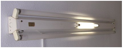
Figure 4. Click here to see a larger picture, or Click here to watch the movie.
It was up to us, the children and especially my wife, to clear the apartment. An incredibly painful job. It also meant a final farewell to the kitchen-light that had been with us for so long. Just for old time sake I opened the lamp for a last time and took some pictures and
even a movie, how silly can you get? The 15th of July this year (2010) my mother died. It definitely meant an end to a period in my life. This page is a kind of a tribute to that period, perhaps difficult to understand for most people, but not for me.

| to top of page | back to homepage |