|
Contents:
|
|
|
Contents:
|
|
When Jim Oostveen, a colleague of mine, had to clear away his storage space,
he invited me to have a look around to see if I could find something useful.
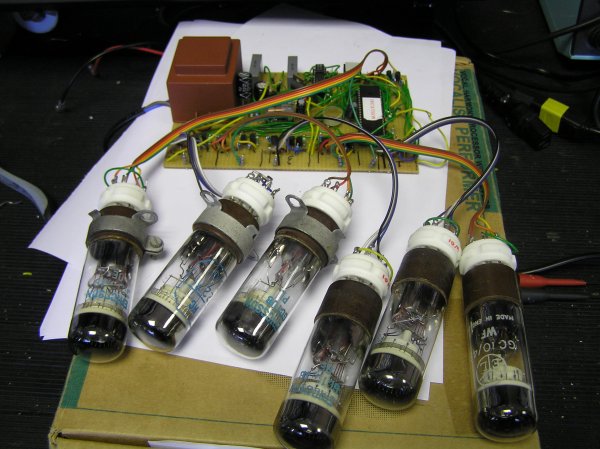
Amongst a few dozen or so of some very interesting radio tubes, I was
lucky to find a nice set of Nixies and a beautiful set of Decatrons (Fig. 1).
Lucky me! Until then I only knew decatrons from pictures on the web. It is not
a device one encounters everyday.
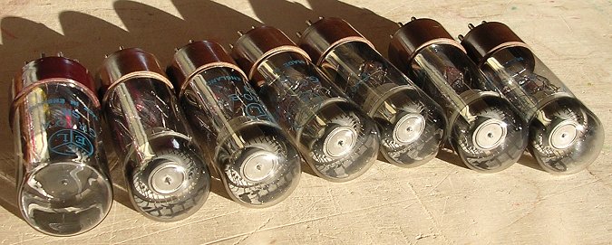
Figure 1. My set of decatron tubes consisting of three GC10B, four GC10/4B and two GR10A tubes
Surfing the web, the most popular thing to make with a decatron seems to be a spinner [1,2,3]. Looking at these spinners I thought it would be a nice idea to make a clock with six (or perhaps even seven) decatrons in a row, with the decatrons showing all kinds of display effects. Instead of simply incrementing the time every new second, it would be great to have a display of forward- and backward-spinning digits, slowly rolling-out to the new time, a little bit like the reels of a slot machine.
Having never encountered them, decatrons are completely new to me. How do
they work, how to interface them to a processor? Instead of working on it
for a few months or so and then writing a new web-page on it, I decided to
present this page in the form of a web-log. The idea is that this page is
expanded every time the project has advanced a bit.
Like the E1T "scaling tube" the decatron preceded the nixie tube, perhaps not by invention, but certainly by application. The most likely reason is that, besides a being a display device, both the Scaling Tube and the Decatron perform the counting function themselves, whereas Nixie tubes require quite a bit of electronics to make them work. They are both small wonders of ingenuity.
The Decatron was first announced in a paper in Electronic Engineering of May 1950 entitled: "The Decatron, A New Cold Cathode Counting Tube" by R.C. Bacon and J.R. Pollard from Ericsson Telephones Research Laboratories, Nottingham, England [4]. The paper discusses the general operation, the performance, and the circuit requirements. The working of the Decatron is best explained in the words of the inventors:
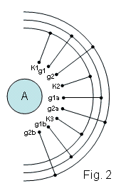
Fig. 2 shows, around the central anode disk A, a number of equi-spaced rods
or wires (on a pitch circle of 20mm. diameter in the case of GC10A). These
wires actually comprise thirty electrodes, of which ten are cathodes, ten are
guide 1 electrodes, and ten guide 2 electrodes. Nine of the cathodes are
connected internally in the sequence shown in part in Fig. 2. The tenth
cathode is isolated and brought out separately, as the output or marking
cathode. The ten guide 1 electrodes are connected internally, g1, g1a, g1b,
etc., and in the same way the ten guide 2 electrodes marked g2, g2a, etc.,
are internally linked. Hence the tube has five outlets, comprising anode,
output cathode, cathode ring, guide 1 ring and guide 2 ring.
It follows from the above argument that by reversing guide 1 and guide 2
connexions the glow can be caused to rotate in an anticlockwise direction.
 A cathode glow on one of a set of inter-connected cathodes, arranged around
a central common anode, is caused to transfer from one position to the next
by application of controlling voltages to intermediate electrodes or "guides".
This arrangement will become clear by considering Figs. 2 and 3.
A cathode glow on one of a set of inter-connected cathodes, arranged around
a central common anode, is caused to transfer from one position to the next
by application of controlling voltages to intermediate electrodes or "guides".
This arrangement will become clear by considering Figs. 2 and 3.
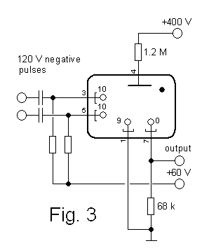 Referring to Fig. 2, together with the simple circuit arrangement of Fig. 3,
let it be assumed that a discharge is taking place between anode A and
cathode k2.
If a negative pulse of 120 volts is applied to the group of
guide 1 electrodes (g1, g1a, etc.) which were originally at +60 volts with
respect to the cathode k2, a transfer of the glow will take place in a
clockwise direction to electrode g1a. That is to say the glow discharge will
transfer preferentially one position clockwise as opposed to two positions
anticlockwise to electrode g1. If it be arranged that simultaneously with the
restoration of guide 1 to +60 volts, a similar pulse is applied to guide 2, the
glow will move clockwise to electrode g2a. The function of the two guide
systems is thus to render certain the direction of motion of the discharge.
When guide 2 is restored to its original potential of +60 volts relative to
the cathode, the glow moves forward to the next cathode k3. This accomplishes
one complete cycle of operation: for each such cycle the illumination moves
one step in a clockwise direction.
Referring to Fig. 2, together with the simple circuit arrangement of Fig. 3,
let it be assumed that a discharge is taking place between anode A and
cathode k2.
If a negative pulse of 120 volts is applied to the group of
guide 1 electrodes (g1, g1a, etc.) which were originally at +60 volts with
respect to the cathode k2, a transfer of the glow will take place in a
clockwise direction to electrode g1a. That is to say the glow discharge will
transfer preferentially one position clockwise as opposed to two positions
anticlockwise to electrode g1. If it be arranged that simultaneously with the
restoration of guide 1 to +60 volts, a similar pulse is applied to guide 2, the
glow will move clockwise to electrode g2a. The function of the two guide
systems is thus to render certain the direction of motion of the discharge.
When guide 2 is restored to its original potential of +60 volts relative to
the cathode, the glow moves forward to the next cathode k3. This accomplishes
one complete cycle of operation: for each such cycle the illumination moves
one step in a clockwise direction.
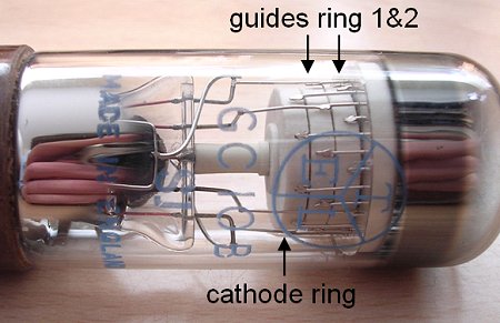
Figure 4. The interior of the GC10B.
The paper beautifully describes the transfer of the glow from one cathode to another. However, it fails to explain why only one cathode ignites. For the reader in 1950 this was probably obvious, for the modern reader it is perhaps less so. Figure 3 shows that the anode is connected to the high voltage supply via a resistor. When the voltage is raised, at a certain moment one of cathode-anode gaps ionizes. Which one of the ten cathodes will ignite, depends on small differences in gap width, asymmetries, the accidental passing of an ionizing particle etc. When the first cathode has ignited, a current will start to flow that will cause a voltage drop over the anode resistor. The voltage drop will lower the anode potential to a value which is too low for the ionization of another cathode-anode gap, but high enough to maintain the glow on the first cathode.
A very simple trick is used to generate a carry signal when the tube has
counted ten input pulses [4]:
When the discharge rests on the single cathode which is connected to a
separate base pin, the current flowing to that electrode will give
rise to a potential difference across a series resistor in the cathode lead
(see fig. 3), so that it is possible to obtain an output pulse coincident
with every tenth input cycle.
The separate cathode is called the "zero" cathode. Note that in contrast
to the E1T scaling tube the decatron does not need any special circuitry
to reset the tube to zero after it has reached nine.
The working of the decatron resembles that of a Charge Coupled Device
(CCD). In a CCD device packages of charge are transported in a potential
well induced by a three phase control gate system. The simplest way to drive
the guides is connecting them to a sinusoidal input signal via a simple RC
phase shifting network. This is the method used in the most popular
decatron gadget on the web: the decatron spinner
Having never worked with decatron tubes before, I did not have a real
"feeling" for them apart from what I learned from the datasheets [5].
I decided to do some simple experiments to see if the tube was really
so simple to operate as the descriptions suggest. The circuit depicted
in Fig. 5 is about the simplest circuit that can be used to test a decatron
tube. When the anode voltage is applied, one of the cathodes will ignite,
or "strike". The anode potential at which one of the cathodes strikes is
called the striking voltage. In my first experiments I used a high-voltage
supply that "only" went up to 320 V. This was just enough to make the tube
strike. I sometimes observed a delay between the application of the
anode voltage and the striking of the tube. When it was dark in the room,
the tube sometimes would not strike at all. Switching on the light usually
ignited the tube. At page 71 in the Ericsson manual we find:
A minimum value for the H.T. supply voltage is quoted by the tube
manufacturers. If a smaller supply voltage than this is used, the tube may
not strike when the voltage is first applied. Since the tubes are not primed,
there may be a delay of about a minute before they strike if a value
of H.T. supply voltage near to the minimum recommended value is employed.
I did not have a clue as to what "primed" meant in this context, but
David Forbes [9] was so kind to explain it:
There are nixie tubes and plasma display panels that have primer
electrodes, which are small cathodes (typically) supplied with full
ionization voltage at a very low current.
The primer's job is to generate enough ions in the envelope that the
ionization of the main cathode will occur instantaneously instead of
waiting for some random cosmic particle to kick it off.
Some other types of tubes had a bit of radioactive krypton gas
introduced to generate ionization.
The manual
does not mention anything about the dependency of the striking voltage on the
illumination conditions. However, the datasheet of the GC10B specifies the
minimum supply voltage as 350 V under normal room illumination, so
the effect must be well known. Obviously my 320 V is well below the
specification for reliable operation.
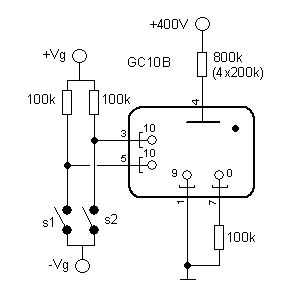
Figure 5. Decatron test circuit
I now have a second H.V. supply (thanks to Wilma, Ronald and Peter), so that I can test the tube under normal conditions. Actually, there is no upper limit for H.T. supply voltage. Once the tube has ignited, the anode potential drops to the "maintaining voltage", which is about 192 V for the GC10B. The maintaining voltage is to a large extend independent of the current flowing, so that the value of the anode resistor can be calculated by application of Ohm's law: Ra = (Vht-192)/Ia, with Vht the H.T. supply voltage, and Ia the anode current. The datasheet specifies a minimum anode current of 250 µA (Vht=400 V and Ra=800 kohm). However, if the tube does not have to run at its maximum specified counting speed, much lower currents may be used. I prefer to use an as low as possible anode current since this will increase the life of the tube.
The life of the decatron tubes is normally many tens of thousands of hours. One of the factors which determines the life expectancy of the tube is the sputtering of material from the electrodes and the deposition of the sputtered material on adjacent cathodes [6]. This will alter the discharge characteristics of the electrodes resulting in a lower counting speed. Additionally sputtered material from the cathodes will darken the inside surface of the glass envelope. A longer life can be obtained by using a low as possible current and by regularly circulating the discharge. I found the lower limit for reliable operation to be 170 µA. For the clock I will start at a save value of 250 µA, and than decrease the current to the minimum value still yielding accurate counting.
 Just for fun I measured the GC10B I-V characteristics with a Tektronix 370A
curve-tracer. A curve tracer is used to characterize semiconductor components.
Basically it is a combination of a variable saw-tooth generator and an
oscilloscope. A saw-tooth shaped voltage is applied to a device under test
and the current through the device is recorded. In order to be able to test
high voltage diodes and transistors, a maximum saw-tooth voltage of 1400 V
can be generated, so it is also ideal for testing tubes! Figure 6 depicts the I-V
characteristic of the GC10B with cathode 0 tied to the common cathodes via
a 100 kohm resistor, and the guides not connected. The curve starts at the origin.
For increasing voltage, the current is basically zero until the tube strikes
at 320 V (point A). The next few measurement points shoot over the I-V
plane, eventually ending in point B. I have to say that I was completely
surprised by this behavior. I have two possible explanations: in the first
place the current and dissipation limiting circuit inside the curve-tracer
can have difficulties with the sudden striking of the tube, resulting
in oscillations. In the second place, it is possible that the negative
impedance characteristic of the tube in combination with interconnect
inductances and capacitances causes an oscillation that quickly dampens.
The negative impedance behavior can be seen for the part of the curve between
B and C. Here, as the current decreases the voltage over the tube increases,
or in other words we have an decreasing current for an increasing voltage.
Observe that under normal operation conditions (Ia=250 µA point B), the
maintaining voltage is 192 V as expected. After the plasma has extinguished
(point C), the current returns to zero, and remains zero going back to zero
volts again. The "looping" of the current near the x-axis is caused by
charging and de-charging of interconnect capacitances.
Just for fun I measured the GC10B I-V characteristics with a Tektronix 370A
curve-tracer. A curve tracer is used to characterize semiconductor components.
Basically it is a combination of a variable saw-tooth generator and an
oscilloscope. A saw-tooth shaped voltage is applied to a device under test
and the current through the device is recorded. In order to be able to test
high voltage diodes and transistors, a maximum saw-tooth voltage of 1400 V
can be generated, so it is also ideal for testing tubes! Figure 6 depicts the I-V
characteristic of the GC10B with cathode 0 tied to the common cathodes via
a 100 kohm resistor, and the guides not connected. The curve starts at the origin.
For increasing voltage, the current is basically zero until the tube strikes
at 320 V (point A). The next few measurement points shoot over the I-V
plane, eventually ending in point B. I have to say that I was completely
surprised by this behavior. I have two possible explanations: in the first
place the current and dissipation limiting circuit inside the curve-tracer
can have difficulties with the sudden striking of the tube, resulting
in oscillations. In the second place, it is possible that the negative
impedance characteristic of the tube in combination with interconnect
inductances and capacitances causes an oscillation that quickly dampens.
The negative impedance behavior can be seen for the part of the curve between
B and C. Here, as the current decreases the voltage over the tube increases,
or in other words we have an decreasing current for an increasing voltage.
Observe that under normal operation conditions (Ia=250 µA point B), the
maintaining voltage is 192 V as expected. After the plasma has extinguished
(point C), the current returns to zero, and remains zero going back to zero
volts again. The "looping" of the current near the x-axis is caused by
charging and de-charging of interconnect capacitances.
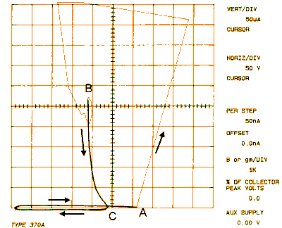
Figure 6. I-V curve of a GC10B measured on a Tektronix 370A curve-tracer.
Using the switches (Fig. 5) it was easy to move the glow around the tube. The sequence S1, S1+S2, S2 makes the glow rotate in one direction, the sequence S2, S1+S2, S1 makes it rotate in the opposite direction. Although the datasheet specifies optimal quide voltages of +Vg=60 V and -Vg=-60 V, it appeared that a reliable glow transfer could still be realized if they are reduced to +/- 20 V. This means that for interfacing the tube to a processor a normal small signal transistor like a BC550 with a BVceo of 100 V can be used. The absolute minimum values for my tube were +Vg=3 V and -Vg=-16 V.
With the switches in Fig. 5 open, there is a current of about 7 µA flowing
Certainly the most popular decatron circuit on the web must be the decatron
spinner. A nice animation of a spinning decatron tube can be seen on Hans Summers
site [7].
If I am not mistaken, the original spinner circuit can be found on
Mike's Electric Stuff pages [8]. The circuit only contains a few components
and the effect is, certainly considering its simplicity, "striking".
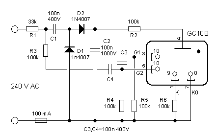
Figure 7. Simple decatron spinner circuit (adapted from the original circuit on Mike's Electric Stuff pages [8])
In Fig. 7 I have reproduced Mike's original circuit with some modifications
to the component values. The circuit consists of two sub-circuits: a voltage
doubler and a phase-shifter. The voltage doubler consisting of C1,C2, D1
and D2 rectifies and doubles the mains voltage so resulting in a DC H.T.
voltage of 450 V. The phase shifter can be found around the circuit consisting
of R3,R4,R5,C3 and C4. All 100 kohm resistors are actually two 47 kohm resistors
in series to half the voltage across each resistor.
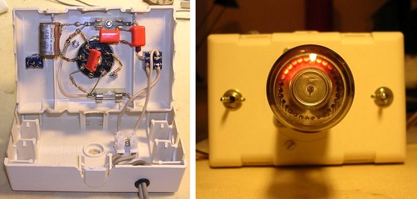
Figure 8. Simple decatron spinner
Please note that this circuit is directly connected to the mains! Contact
with any part of the circuit can be lethal. The circuit should be build
in a completely isolated box. Also remember that the capacitors will remain
charged after the mains has been disconnected. With these kind of directly
mains fed circuits one can nor be too careful!
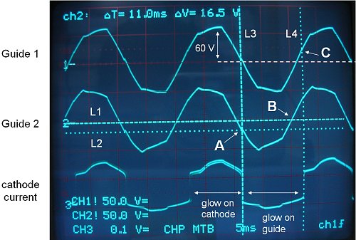
Figure 9. Working of the phase shifter circuit in the decatron spinner.
To better understand the working of the phase shifter, I recorded the guide
voltages on the scope (Fig. 8). For this measurement I used two transformers
in cascade (240 V->6 V and 6 V->240 V) to isolate the circuit from the mains.
A small 1k resistor was added in
series with the cathodes so that I could see when the glow was resting
on the cathodes or on the guides (lower trace in Fig. 9).
When the voltage on guide 2 drops to ca. -16 V, the glow shifts from the
cathode to quide 2 (point A). Due to the integrating network C4, R5 the voltage
on guide 1 lags behind on the voltage on guide 2. At one point the voltage
on quide 2 will increase again and with the voltage on guide 1 lagging
behind, at a certain point the glow will transfer to guide 1. Finally when
the voltage on guide 1 rises 16 V above the cathode potential, the glow
transfers to the next cathode. Reliable and very simple!
I have to say that I do not really understand the function of C3. To my
opinion it can be omitted by increasing the value of R3, but I did not
bother to test it.

Any interface of the decatron to a CPU has to perform at least two functions.
In the first place the CPU has to control the voltages on the guides so that
the glow can rotate clock-wise or anti- clock-wise. Secondly, since a
decatron is essentially a counting device, there must be some means to
synchronize the counts on the tube to a counter in the CPU. For the
synchronization there are basically two possibilities: 1. The CPU can reset
the tube to zero, so that it forces the glow to a known position, 2. The CPU
can detect the glow as it passes the zero cathode. Obviously, also a
combination of the two possibilities is possible.
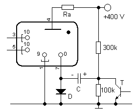
Figure 10. Idea to generate a reset pulse without the need for a negative power supply.
To reset the glow to the "zero" cathode, a negative pulse of about 100 V has
to be applied to cathode zero with respect to the other cathodes. To avoid
an additional negative supply voltage, the simple circuit of Fig. 10 can be
used. When T1 is not conducting, C1 will be charged to 100 V. The charge
current as well as the cathode current will flow via diode D to ground. When
T is switched on, the positive plate of the capacitor will be connected
to ground so that the negative plate will drop to -100 V below ground with
D blocking. To my humble opinion this approach has two drawbacks. In the first
place it requires a high voltage switching transistor. In the second place, if
the reset fails, we still do not have any way of knowing on which cathode the
glow rests. For these reasons I prefer to synchronize the tube by detecting
the glow on cathode zero.
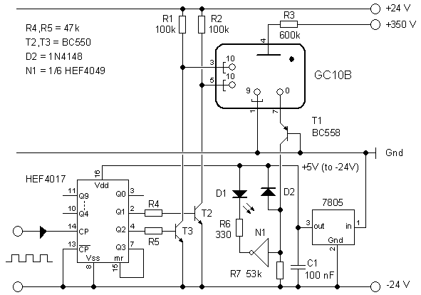
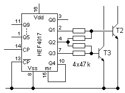
Figure 11. Breadboard circuit used to test the interfacing of the decatron tube to a digital environment.
The circuit depicted in Fig. 11 was used to test the CPU interface. The circuit
uses three supply voltages: +350 V, + 24 V and -24 V with respect to ground.
The cathodes of the GC10B are connected to ground. Pull-up resistors R1 and R2
keep the guides at +24 V when they are not activated. Transistors T2 and T3
pull the quides to -24 V when activated. In this test circuit a HEF4017
Johnson counter and a HEF4049 inverter are used to simulate the CPU
outputs and inputs. The digital logic is
fed from an auxiliary power supply which is derived from the -24 V supply
using a standard 7805. So the -24 V is the ground for the digital circuits.
The maximum input voltage of a 7805 is 35 V, so if needed the supply voltages
can still be increased a little. The only thing we need to keep track of is the
dissipation. For an input voltage of 24 V the voltage drop
over the 7805 is 24-5=19 V. The thermal resistance of a TO-220 package to
ambient is something like 70 K/W. If we want to limit the temperature of the
7805 to 50C with an ambient temperature of 20 C (so a 30 C increase) we have to
limit the dissipation to 30/70=420 mW. With a voltage drop of 19 V this means
a maximum current of 0.42/19=22 mA. For the processor I had a 16F874 of 16F876
in mind. They consume about 10 mA at 20 MHz clock, so we are well within the
safe dissipation range.
Figure 12. Breadboard test circuit of Fig. 10 in practice.
The common cathodes have all been tied to ground. As mentioned before, the
"zero" cathode is used to detect the position of the glow. Transistor T1 is
used in what is called a "common base" configuration. Its working can
easily be understood if we first consider the collector disconnected. In that
case the emitter-base junction of T1 will be forward biased, and the current
flowing out of cathode zero will flow through the forward biased emitter-base
junction to ground. So cathode zero "sees" a potential Vgnd (Vgnd+0.8 V to be
precise). With the cathode of T1 connected, almost all the emitter current
will flow out of the collector into R7 ( Ic=Ie*hFE/(hFE+1) so for large
hFE, Ic=Ie). In this way current and potential have been decoupled: the cathode
still sees a ground potential, while the cathode current is redirected through
R7 to -24 V.
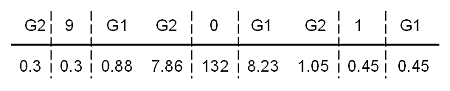
Figure 13. Current flowing out of cathode zero for the glow resting on different positions around cathode zero (Va=350 V and Ra=600 kohm).
The "zero" cathode current causes a voltage drop over R7
which is used to signal the
position of the glow. The value of R7 needs some consideration. The problem is
that already when the glow is approaching the zero cathode a considerable
current starts to flow out of cathode zero. The current is caused by
electrons from the discharge on one of the adjacent guides which accidentally
hit the "zero" cathode. Figure 13 gives the "zero" cathode current for different
positions of the glow, for a 350 V anode voltage and an 600 kohm anode resistor.
We find that when the glow rests on one of the guides immediately adjacent
to the "zero" cathode the cathode current is approximately 8 µA. The
value of R7 needs to be such that this current does not result in a erroneous
"1" reading by the CPU. According to the PIC datasheet the input high and
low levels are defined as: "0" < 0.8 V and "1" > 2 V. If we take R7=53 kohm,
a glow on one of the adjacent guides will result in a voltage drop of
8 µA*53 kohm = 0.424 V, what the PIC will read as a "0". When the current is
resting on cathode zero the voltage drop will be 132 µA*53 kohm=7 V. However,
when the voltage drop increases beyond 5 V, D2 will become forward biased and
limit the voltage drop to 5 V. This will protect the input of the PIC for
any over-voltage. In the test circuit of Fig. 11 LED D1 will light when the
glow is resting on cathode "zero".
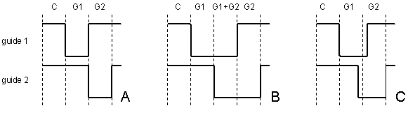
Figure 14. Different quide driving schemes.
When I first built the test circuit of Fig. 11, I thought to be clever, and
implemented the quide driving scheme depicted in Fig. 14B.
 This four phase
driving scheme is obtained from the modified circuit on the left. The idea
was that in this way there is a well defined overlap between the
quide 1 low phase and guide 2 low phase. As it turned out this driving
scheme resulted in an irregular spinning of the tube. What happens is the
following: during the C phase the glow is resting on the cathode. When guide 1
becomes low (G1 phase) the glow transfers to guide 1. In the next phase guide
2 also becomes low. In this phase where both guides are low, the glow
sometimes stays on guide 1 and sometimes transfers to guide 2, resulting in
an irregular spinning. A perfect result is obtained with the driving scheme
that is implemented in Fig. 11, and depicted in Fig. 14A. In theory a small
overlap between guide 1 low and guide 2 low is required to prevent the glow
from turning back to the last cathode (fig. 14C).
In the circuit of Fig. 11 no special
precautions have been taken to guarantee such an overlap. The capacitances
of the guide electrodes probably take care of that, resulting in a perfect
spinning of the glow. In the final CPU driven version I will first try the
simple driving scheme of Fig. 14A. If that doesn't work I will implement
something like Fig. 14C.
This four phase
driving scheme is obtained from the modified circuit on the left. The idea
was that in this way there is a well defined overlap between the
quide 1 low phase and guide 2 low phase. As it turned out this driving
scheme resulted in an irregular spinning of the tube. What happens is the
following: during the C phase the glow is resting on the cathode. When guide 1
becomes low (G1 phase) the glow transfers to guide 1. In the next phase guide
2 also becomes low. In this phase where both guides are low, the glow
sometimes stays on guide 1 and sometimes transfers to guide 2, resulting in
an irregular spinning. A perfect result is obtained with the driving scheme
that is implemented in Fig. 11, and depicted in Fig. 14A. In theory a small
overlap between guide 1 low and guide 2 low is required to prevent the glow
from turning back to the last cathode (fig. 14C).
In the circuit of Fig. 11 no special
precautions have been taken to guarantee such an overlap. The capacitances
of the guide electrodes probably take care of that, resulting in a perfect
spinning of the glow. In the final CPU driven version I will first try the
simple driving scheme of Fig. 14A. If that doesn't work I will implement
something like Fig. 14C.
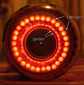
Figure 15. Difference a glow resting on a cathode or on a guide.
When I had the decatron spinning, I observed that the glow also partially
rests on the anode. Furthermore there was a difference in the glow near
the anode when the glow was resting on an anode, or on one of the guides.
I have tried to capture the effect in Fig. 15. The difference
disappeared when the guide driving voltages where increased to +/- 60 V (Fig. 16).
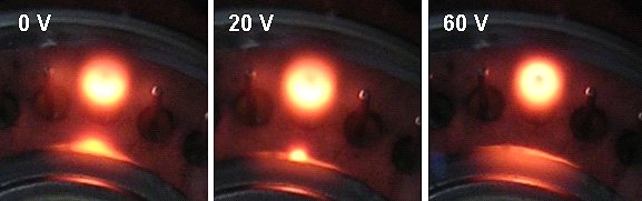
Figure 16. The pattern of the glow resting on a cathode for different guide bias values.
Designing and making a suitable case is always the biggest problem for every new clock I build. For this particular clock, I was looking for an original way to mount the tubes in such a way that the beautiful construction of the interior of the decatron tubes would also be visible. This triggered the idea to mount the tubes vertically! This gives an optimal view on the interior of the tube, while a mirror placed at a 45 degree angle at the front of the tube will allow for reading of the tube.
In this way the clock can simply be attached to the wall as a kind of electronic painting. This idea additionally solves another problem: my house is slowly becoming saturated with clocks. One of the few rooms that is still without one of these "wonders of technology" is the toilet. An exotic and interesting clock with all kind of visual effects will certainly make nice change for the eternal birthday calendar. A "toilet clock" has the additional advantage that the tubes can be switched off when the toilet is not occupied. A simple LDR can be used to check if the light is on or off. This will greatly increase the life of my precious decatrons.
So much for the case. In the mean time I have decided on the
processor I am going to use. Being a bit of a PIC addict, I selected the
16F874, mainly because of the large number of IO pins that I will
need (ca. 24).
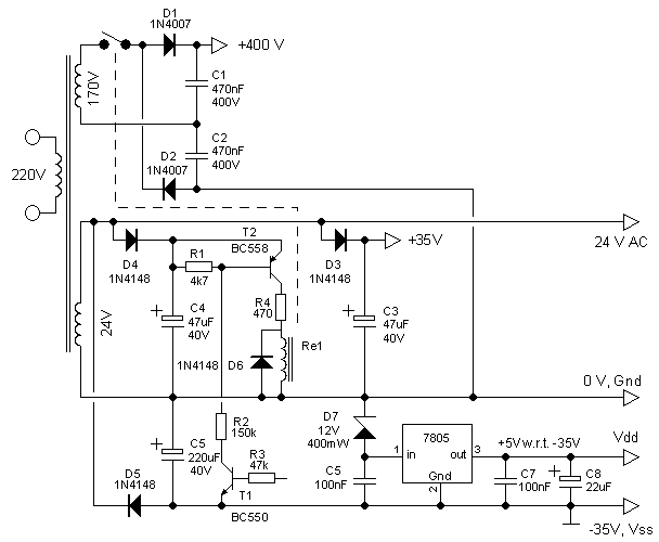
Figure 17. Schematic diagram of the power supply
Figure 17 depicts the circuit diagram of the power supply for the clock. It is based on a nice small transformer I found at "Radio Service Twente" [10]. They have a great stock of surplus and "out of production components", and if you are ever in Den Haag (The Hague) [11], you should visit them. The transformer has two secondary windings: 24 V and 170 V with a tap at 60 V. There was no current rating for these windings but the DC resistances are 36 ohms and 1400 ohms respectively. Lets assume for the moment that each decatron will draw ca. 300 µA. Then the total HT current consumption will be less than 2 mA, resulting in a voltage drop over the 170 V winding of 2.8 V, resulting in a resistive loss of only 5.6 mW, which should be no problem at all. I compared the 24 V winding with another 24 V transformer I had lying around. This small transformer had a secondary resistance of 140 ohm, and is rated at 60 mA. This would imply that my transformer should be rated at (140/36)*60 mA= 240 mA. To me this seems rather a lot. I will try to keep the current consumption below 50 mA.
The simple voltage doubler circuit formed by D1,D2,C1 and C2 is used to generate the high tension anode supply for the decatrons. The unloaded output voltage is 430 V. The high tension supply is switched on and off by S1, which is one of the contacts of relay Re1.
 The secondary 24 V winding is used to generate the +/- 35 V guide voltages
and the 5 V supply voltage for the digital ICs. Just as in the interface
test circuit in one of the previous sections, the 5 V supply is positioned
against the -24 V supply in such a way that the -35 V guide voltage is at the
same time the Vss for the digital ICs. To avoid confusion is will call the real
0 V Gnd, the ground for the digital ICs (= -35 V guide bias) Vss, and the
positive supply voltage for the ICs (ca. -30 V with respect to Gnd) Vdd.
35 V is very near or even in excess of the maximum input voltage allowed
for the 7805 regulator. That is why a 12 V zener diode is used to reduce
the input voltage of the 7805 to a safer 24 V.
A 24 V relay uses far less current than a comparable 5 V relay.
That's why I used a 24 V relay to switch the HT on and off.
The relay I use has a DC resistance of 1K2. With a 470 ohm resistor in series
the current consumption by the relay is 21 mA. Since the supply voltage
for the digital stuff was derived from the negative phase of the 24 V,
the relay is fed from the positive phase, resulting in a more symmetrical
loading of the transformer. The simple circuit around T1 and T2 interfaces the
relay to the processor. To provide a more stable guide voltage, the relay
has its own rectifying circuit consisting of D4 and C4.
The secondary 24 V winding is used to generate the +/- 35 V guide voltages
and the 5 V supply voltage for the digital ICs. Just as in the interface
test circuit in one of the previous sections, the 5 V supply is positioned
against the -24 V supply in such a way that the -35 V guide voltage is at the
same time the Vss for the digital ICs. To avoid confusion is will call the real
0 V Gnd, the ground for the digital ICs (= -35 V guide bias) Vss, and the
positive supply voltage for the ICs (ca. -30 V with respect to Gnd) Vdd.
35 V is very near or even in excess of the maximum input voltage allowed
for the 7805 regulator. That is why a 12 V zener diode is used to reduce
the input voltage of the 7805 to a safer 24 V.
A 24 V relay uses far less current than a comparable 5 V relay.
That's why I used a 24 V relay to switch the HT on and off.
The relay I use has a DC resistance of 1K2. With a 470 ohm resistor in series
the current consumption by the relay is 21 mA. Since the supply voltage
for the digital stuff was derived from the negative phase of the 24 V,
the relay is fed from the positive phase, resulting in a more symmetrical
loading of the transformer. The simple circuit around T1 and T2 interfaces the
relay to the processor. To provide a more stable guide voltage, the relay
has its own rectifying circuit consisting of D4 and C4.
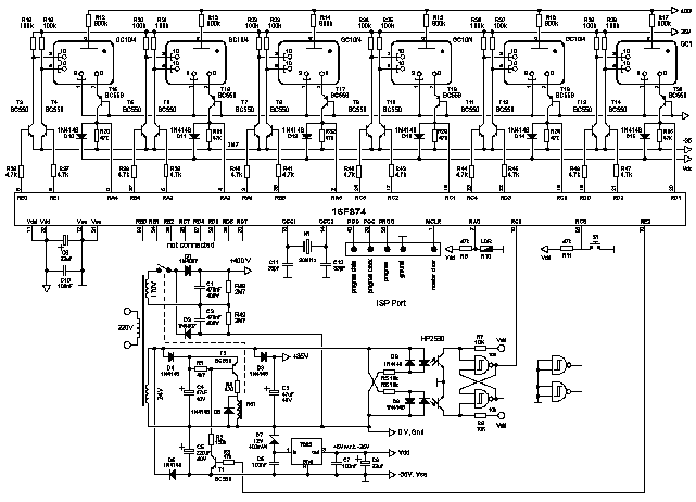
Figure 18. Total circuit diagram of the decatron clock. Clicking on the figure will open a window with a detailed circuit diagram in pdf format.
After the discussion of the CPU interface, the circuit diagram for the clock
itself will hold no surprises (Fig. 18). Just as in most of my other clocks,
the 50 Hz timebase signal is derived from the mains by means of two
opto-couplers and a NAND Flip-Flop. An LDR is used to check if the light
in the toilet is on or off. The LDR is connected to the PICs AD converter via
one of the analog inputs, so that the light on and off threshold can be chosen
under software control. A single push-button is used to set the time.
The distribution of the guides and cathodes of the I/O ports at first sight
seems rather random. Connecting them in this way however, resulted in the
simplest wiring. Figure 19 finally shows the front- and back-side of the
finished PCB excluding the high voltage supply, which will be added on a
separate PCB.
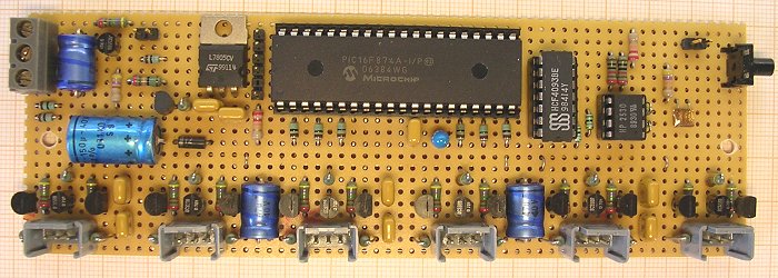
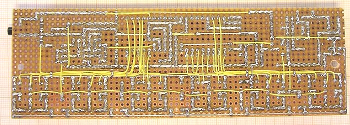
Figure 19. Front- and backside of decatron clock PCB
| guide 1 | guide 2 | cathode | |
| sec*1 | PORTD,0 | PORTD,2 | PORTD,1 |
| sec*10 | PORTC,4 | PORTD,3 | PORTC,3 |
| min*1 | PORTC,5 | PORTC,2 | PORTC,1 |
| min*10 | PORTE,0 | PORTE,1 | PORTA,4 |
| hrs*1 | PORTB,4 | PORTA,3 | PORTA,2 |
| hrs*10 | PORTA,1 | PORTB,5 | PORTA,5 |
| LDR | PORTA,0 | A-inp. | light = low |
| switch | PORTC,6 | D-inp. | push = "0" |
| 50 Hz | PORTC,0 | D-inp. | - |
| relais | PORTE,2 | D-outp. | HV on = "1" |
Figure 20 depicts the complete clock. Remember that the clock will be hung against the
wall with the front of the tubes facing down. A small mirror will allow for simultaneous
viewing of both the front as well as the interior of the tubes. For the octal bases I used
six old sockets from Pirani pressure gauges. The tubes are clamped in what is known as
"tool clamps". The small PCB to the left holds the high-voltage supply and the HV on/off
relay. In Fig. 20 the clock is connected via the In System Programming (ISP) connector
to Wouter Ooijens ISP programmer [12].
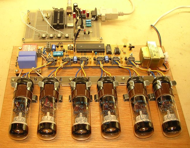
Figure 20. Assembled clock connected to my "In System Programming" board.
It is the task of the software (which can be downloaded at
the end of this page)
to keep track of the time and to control and drive the
decatron tubes.
To make the clock more interesting and attractive to look at, the clock
can make the glow in the tubes spin or rotate. The spin and rotation actions
are combined in different display effects.
During rotation the glow moves at
a constant speed to the new resting position. During a spin the glow starts
rotating at a very high speed and then "rolls out" until it stops at the next position.
Both clockwise (forward) and counter clockwise (reverse) spinning and rotation is
possible.
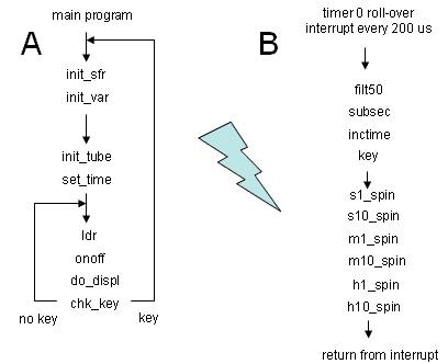
Figure 21. Flow-diagram of the main program (A) and the interrupt service routine which is called every 200 µs on a timer0 roll-over (B). The names refer to the subroutines called.
The main program (Fig. 21A) is very simple and performs the non-time critical tasks. The main program is interrupted by a roll-over (transition from FFH to 00H) from timer0. The clock input of timer0 is connected to the internal processor clock running at 20 MHz/4=5 MHz, with a cycle time of 1/(5 MHz)=200 ns, via the prescaler set at 4. A roll-over of timer0 thus occurs every 200ns*4*256=204.8 µs. The interrupt service routines (Fig. 21B) perform a number of time critical task such as the actual control of the tubes.
The main program first-of-all initializes the special function registers in routine "init_sfr", followed by the program variables in "init_var". Next the tubes are initialised or rather synchronised. Remember that when the tubes ignite, the position of the glow is unknown. By rotating or spinning the glow at least one full circle, the glow passes "cathode zero" which is detected by the program so that from then on the position of the glow is known. This procedure is discussed in detail below in the description of the spin and rotate routines. In the main program the synchronisation of the tubes is done in "init_tube".
Next, the clock is set to the correct time in the routine "set_time". For this the one push-button procedure is used that I use in all my clocks. When the push-button is pressed, the minutes start advancing at a pace of one per second. When the button is pressed again the minutes stop advancing and now the hours start advancing. Pressing the button again stops counting of the hours. When the button pressed for the fourth time the clock is switched on.
The main program now enters a loop that takes care of three tasks: switching of the tubes when it is dark ("ldr","onoff"), initiating the different display effects for every new minute ("do_displ"), and detection of the pressing of the push-button ("chk_key"). When the push-button is pressed the clock is reset.
In normal operation the seconds tubes count in the normal fashion from 0 to 59. When the
seconds advance from 59 to 0, the S10, M1, M10, H1 and H10 tubes move to their new
position while displaying a particular spin of rotation sequence. There are 10 different
sequences. The routine "do_displ" initiates these display effects. The routine checks
the auxiliary new seconds flag "newsec2". When a new second is detected, the glow
position of the seconds tubes is adjusted. However, on the transition to a new minute
the routine initiates the display effects by setting up the
appropriate control bytes
for the spin/rotate routines of the interrupt service routines. A separate
subroutine "show_1, show_2, ....." is used for each of the ten display effects.
Which routine is called depends on the value of the lower nibble of variable "MIN"
As mentioned before, the idea is to hang this clock on the wall of the toilet. This means that the tubes only need to be switched on when there is actually somebody using the toilet. Since people normally switch the light on when they use the toilet, a simple Light Dependent Resistor (LDR) can be used as sensor. As the name suggests, the resistance of an LDR depends on the light on the LDR. In the dark the resistance is usually several mega-ohms. When illuminated the resistance drops to a few-hundred ohms, depending on the light intensity.
The LDR in combination with Rxx form a voltage divider which is connected to PORTA,0.
When it is light, the resistance of the LDR is low and the voltage on PORTA,0 low.
When it is dark, the resistance of the LDR is high, and so is the voltage on PORTA,0.
With Rxx = 47 kohm the threshold between light and dark was found to be somewhere
around 1V. PORTA,0 is switched as analog input and internally connected to the AD
converter of the PIC processor.
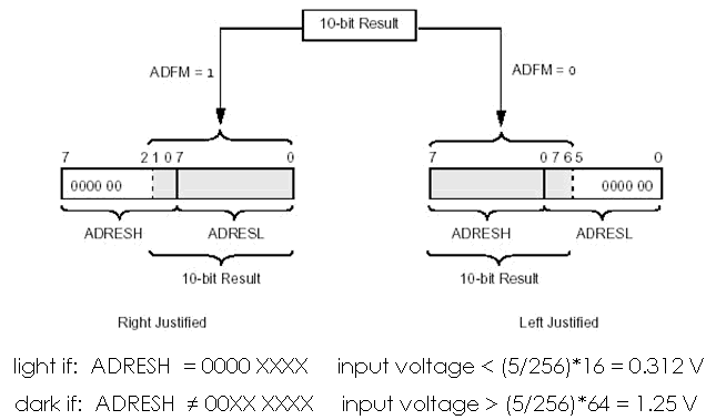
Figure 22. Distribution of the 10-bit AD result over the bytes ADRESH and ADRESL depending on the value of bit ADFM
The result of the AD conversion is a 10-bit value. To make things a little bit simpler I have used a trick to reduce the resolution of the AD converter to 8-bits. The ADFM bit is used to determine how the 10-bit result from the AD conversion is distributed over the two AD converter result bytes ADRESH and ADRESL (Fig. 22). When ADFM=0 the result is what is called "Left Justified" meaning that the eight most significant bits from the AD conversion are stored in ADRESH, while the remaining two least significant bits are stored in ADRESL. We now ignore the data in ADRESL, and only use the data in ADRESH.
When the input (PORTA,0) is 0V, ADRESH=00H, and when the input is 5V, ADRESH=FFH. So every count from ADRESH represents 5/256=0.01953125 V. To build in an hysteresis between light on and light off, all input voltages below (5/256)*16=0.312 V are defined as "light", while input voltages higher than (5*255)*64=1.25 V are regarded as "dark". This definition makes checking for these values very easy since values less than 16 satisfy (11110000.AND.ADRESH)=0, and values higher than 64 satisfy (11000000.AND.ADRESH)<>0.
For input voltages less than 0.312 V (light) the "LIGHT" flag is set. For input voltages
higher than 1.25 V the "DARK" flag is set. For values between those two limits both flags
are cleared. All these actions are performed by routine "ldr".
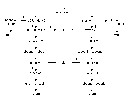
Figure 23 Flow diagram of the routine "onoff" which switches the tubes on and off.
Knowing my youngest son Daan (7), I guessed that he would like to sit in the dark and see the tubes spin. Therefore a delay was built in between the LDR becoming dark and the tubes being switched off. The delay (in seconds) is the program constant "SECDRK" which is set at 180 (3 min). Also a delay between the LDR becoming illuminated and the tubes being switched on was included. This delay ("SECLHT") is set at one second.
The on- and off-switching of the tubes is performed by routine "onoff".
Figure 23 depicts the flow diagram for routine "onoff". It is pretty straight forward,
and uses the additional new second flag "newsec3". Counter "tubecnt" is used to
count the seconds in the specified delays.
The beating heart of the program is the interrupt service routine "tmrint" (Fig.21B) which is called every 200 µs on an interrupt generated by a roll over from timer0 (20 MHz X-tal, prescaler=4). After saving the working registers W, STATUS and PCLATH in routine "push", the interrupt service routine in turn calls another set of routines which perform tasks which are time critical: "filt50", "subsec", "inctime", "key", "s1_spin", "s10_spin", "m1_spin", "m10_spin", "h1_spin", "h10_spin".
The routine "filt50" polls the 50 Hz mains input frequency and filters out any transients and other irregularities. When a new and valid 50 Hz period is found the "NEW50" flag is set.
The routine "subsec" checks, and if required resets the "NEW50" flag, and counts down the 50 Hz periods into seconds. When a new second is found, the new second flags: "newsec1", "newsec2" and "newsec3" are set. These flags are used by the time keeping routine "inctime", the display controller "do_displ" and the tube saver "onoff" routines respectively.
The routine "inctime" checks the "newsec1" flag, and if set increments the time as kept in variables "HRS", "MIN" and "SEC". The routine only starts incrementing the time when the "GOT" (GO Time) flag is set. For the decimal incrementation of the time subroutine "incwdec" is used. This routine performs a decimal incrementation of W.
The subroutine "key" processes and debounces the push-button. When the push-button is pressed during "KEYREL" consecutive calls to "key", the "NEWKEY" flag is set. The program "KEYREL" is set to 030H corresponding to a debounce time of 48*200 µs ca. 10 ms. The "NEWKEY" flag has to be reset by the main program.
Furthermore the spin routines which control the individual tubes are a part of the
interrupt dervice routine. These routines will be described in the next section.
The spinning and rotation of the glow in the tubes is controlled by a separate routine for each tube. The routines are: "s1_spin", "s10_spin", "m1_spin", "m10_spin", "h1_spin", "h10_spin". Each of these routines is called every 200 µs. The "do_displ" routine in the main program communicates with these routines via a set of variables. For each routine an identical set of six variables is used. As an example the variables for the routine that controls the seconds*10 tube ("s10_spin") are: "S10_NOW", "S10_NXT", "S10_Z", "S10_CNT", "S10_REL", "S10_BIT".
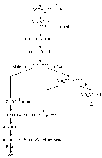
Figure 24. Flow diagram for the s10_spin routine. The other spin routines are identical
Figure 24 depicts the flow diagram for the spin routines. Upon call the routine first
checks if something has to be done at all ("GOR"=1). If so, the routine decrements
the delay counter "S10_CNT". When the counter has reached zero, it is reloaded with
"S10_REL" and the glow is advanced one position. This is done by routine "s10_adv".
The routine "s10_adv" advances the glow by one position (a cathode or guide) in
forward or reverse direction depending in flag "FR". Additionally the routine
performes a number of other tasks which will be discussed later in the discussion
of the "s10_adv" itself. Next the routine checks if this was a rotation or spinning
operation. Lets assume for the moment is was a rotation. in that case the routine
first checks if at this moment the glow is resting on a cathode. If so it checks
if the current cathode position corresponds to "S10_NXT. If this is the case, the
rotation operation is finished. This means that the "GOR" flag is cleared, and that
if the "QUE" flag is set, the "GOR" flag of the next digit is set.
If it was not a rotation but a spin operation, the routine checks if the delay
reload value has already reached 0FFH (slowest speed). Only when it has
reached 0FFH the routine checks if the glow is resting on the next cathode position.
If the reload value has not reached 0FFH yet, "S10_REL" is incremented.
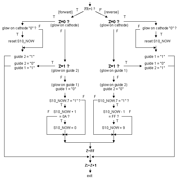
Figure 25. Flow diagram for the s10_adv routine. The other advance routines are identical
The flow diagram for the advance routines is given in Fig. 25. The seconds*10 digit is again used in the example. The main purpose of the routine is to advance, either in forward or in reverse direction, the glow one electrode. For a forward advance this means from cathode->guide1, guide1->guide2 and guide2->cathode. For a reverse "advance" this means from cathode->guide2, guide2->guide1 and guide1->cathode. The variable "S10_Z" keeps track of the location of the glow: "S10_Z"=0 cathode, "S10_Z"=1 guide1, "S10_Z"=2 guide2. The variable "S10_NOW" holds the actual number being displayed on the tube.
The routine is split into two almost identical parts: one for the forward motion, the other for the reverse motion. If we follow the left branch of the flow-diagram in Fig. 25, we see that the routine first checks if the glow is resting on a cathode. If the glow rests on a cathode, it next checks the "cathode input" to see if the glow is accidentally resting on cathode 0. IF so "S10_NOW" is initialized. In this way the routine performs its other important task, namely the synchronisation of the software position counter "S10_now" with the actual position of the glow. Remember that after switching on the tube, the glow will ignite on a random, unknown cathode. In this clock I did not implement a reset circuit. Instead, by rotating the clock at least one full circle during initialisation after a power-up of the tubes, "S10_NOW" is synchronised with the glow position. In fact every time the glow passes cathode 0 the counter is updated.
When the routine finds that the glow is resting on
guide 2 (Z=2), the glow is moved to the next cathode by making guide 2 low again and "S10_NOW" is
incremented, but only if the most significant bit of "S10_NOW" is zero. Why is that ?
To explain this lets first recall the initialisation procedure: first the high voltage is connected
to the decatrons. This will cause a random ignition of one of the cathodes. The software next performs
a spin operation on all tubes. This will certainly initialise the counter "S10_NOW". The problem
with this procedure is that, as mentioned before, it sometimes may take some time for a tube to ignite,
especially if it is rather dark and the tube is cold. So worst case the spin operation is over before
the tube has ignited. In that case "S10_NOW" will not be properly initialised. A simple trick is used to
solve this problem. "S10_NOW" is given the initial value of 0FFH. By only incrementing "S10_NOW" when
the highest significant bit of "S10_NOW" is zero, or in other words when "S10_NOW" has been
initialised because the glow has moved over cathode 0, the spin routine keeps on spinning until
the glow has ignited and passed cathode 0 once! Simple but effective. Variable Z is cleared by first making
it -1 (0FFH) and then incrementing it to zero. It is important to realize that cathode 0 not necessarily
needs to correspond with the "zero position". If for instance for practical reasons cathode six is facing
upward, the reset value of "S10_NOW" can be selected such that the software thinks that cathode 6
represents zero.
With the circuit and the software finished, the remaining task is to finish the case. The most important element still missing is the mirror that will be placed at a 45 degree angle at the top (now the bottom) of the tubes to allow for reading of the digits when the clock is in vertical position. The problem with a normal mirror is that it gives a double reflection, one at the front side of the glass and one at the actual mirror layer. A better result is obtained with a mirror which only reflects on the frontside of the glass. Such a mirror can "easily" be made by evaporating a thin layer of aluminium on a clean plate of glass. A readout dial can then easily be made by etching the numbers in the thin aluminium layer. So this will be the job for the next weeks !
The Software for the decatron clock as described on this page can be
downloaded here.
The compressed file contains
the following files:
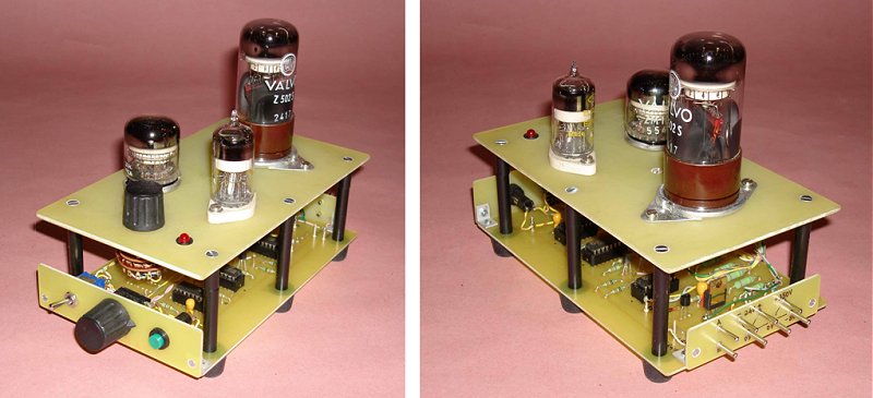
Mark Ayres version of the dacatron clock waiting for a suitable case
The decatron spinner as made by Dusan from Germany.