|
Contents:
|
|
|
Contents:
|
|
Electronics has always been a part of my life. My father (and his father before him) was an active electronics hobbyist who was always collecting parts, and at least during the first ten years of my life, was always working on one project or the other. Looking back I think that his hobby was only partly driven by a fascination for electronics, for the other part he just wanted to make things because he could not afford to buy them. In the fifties and sixties, Holland was still recovering from the war, and people first of all spend their money on the necessities of life rather than on luxurious goods like (portable) radios and televisions. When later in life he had the money buy these things, his active involvement in electronics ceased, although his interest in it remained for the rest of his life.
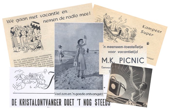
Figure 1 People in post-war Holland were obsessed by the idea of a wireless
portable receiver.
This story about my father is rather exemplary for the electronic hobby scene in the post-war period in Holland. During the war the Dutch had to handover their radios to the Germans in return for a worthless receipt. In this way the Germans hoped to prevent the people from listening to the radio transmissions from the allied forces in England. Many people however, built a clandestine radio hidden in an unsuspicious object like a book. My grand father for instance had a radio built in the family harmonium. When, towards the end of the war it became difficult to get anode batteries, the crystal set receiver of my father (using a cats whisker) was used to listen to “Radio Vrij Oranje”.
When Holland was liberated in 1945, the Germans left a plundered country behind them, with half of its population almost starved to death. People were in want for everything, and food and many goods where put on rations for several years. It was a difficult period, especially for young people like my parents. Since so many young men had died, the remaining had to serve long military duties. My father for instance served for three years as a radio communications officer. At the same time, people heard for the first time of the technical progress that had been made by the allies during the war. It is understandable that developments like television, radar, the atomic bomb and portable radio stimulated the imagination of young and old. On top of that, the enormous progress in solid-state physics as a result of radar detector development accumulated in the invention of the transistor in 1948. However, for many years luxury goods like (portable) radios and gramophones remained beyond the budget of ordinary people. It is therefore not surprising that many people tried their hand at building these goods themselves.
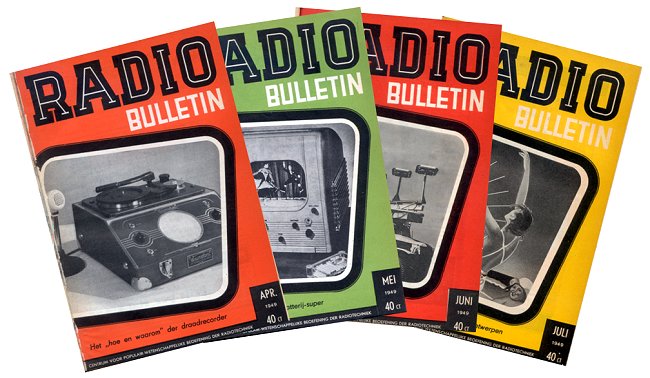
Figure 2 Covers from the 1949 edition of “Radio Bulletin”, the year that “Radio Bob” was published.
The Dutch radio and electronic hobbyist magazine “Radio Bulletin” was a beacon for all those people. It published schematics and detailed construction instructions and discussed recent developments in science and electronics. Radio Bulletin was affiliated with the trading company “AMROH” which supplied the components needed for the designs in Radio Bulletin. The whole period can be characterized as a period of optimism, enthusiasm and wonder over all the new developments. During the recent two decades, electronics has undergone a tremendous development: from something very special, expensive, and fascinating, it has become a black box which is fabricated by somebody in China, at a price so low that in most cases it is just little more than a consumable. Undoubtedly this is the reason why everything related to Radio Bulletin and AMROH from the fifties and sixties has such a very special meaning to many electronics hobbyists of my age and older. AMROH parts are highly collectable and huge prices are paid for simple components like coils.
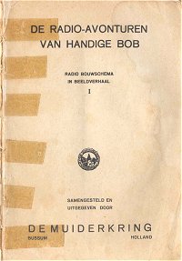 Back in 1949 a small booklet containing a picture novel entitled “The adventures of Radio Bob” (“de Radio Avonturen van Handige Bob”) was published by “de Muiderkring”, who also published Radio Bulletin. It is the story of Radio Bob, who after having built his own crystal set receiver encounters an adventure with a gang of smugglers. The story itself is not very special, nevertheless the story breaths the atmosphere of the fifties. To me the booklet is very special. When I was born in 1961 it was already almost ten years old. My first recollection of it was during a period when my father was in hospital for a period of about seven weeks. I could not have been older than eight years myself, and I recollect that I was completely fascinated by it. After I had found the necessary parts in the stuff of my father, I managed to built the receiver and it actually worked. Over the years I had almost forgotten the book, when some years ago I found it again. It was as if I encountered an old friend.
When I red the book as an eight year old it was already in a pretty bad condition, and the past thirty years did not improve matters. That is why some time ago I decided to scan the whole booklet to save it “for future generations.” Ever since I have my own web site, it has been my plan to spend a page on it. Recently I found some interesting background material that I have added to complement the story itself.
| to top of page | back to homepage |
The full title of the booklet is “De Avonturen van Handige Radio Bob”. Translated, this reads “The adventures of handy Radio Bob”. I discussed this translation with a native English speaker, and he thought that “handy” was not really the right expression to use here. Since he could not come up with an alternative, I decided to simply translate it into “The adventures of Radio Bob.”
The story itself is about a boy named Bob, aged ca. 15, and most probably living in Amsterdam. Bob is an “early to bed, early to rise ……” type of guy, the prototype of a fair headed over-active boy scout. In fact the type of person that the Germans were so fond of during the war! It shows that at that time their ideals were probably more common than we prefer to remember. Anyhow, the war had just ended and from the drawings we get a picture of how impoverished Holland was in that period. Even from the black-and-white illustrations it is clear that everything is in want of a bit of painting. Bob’s favorite magazine is “Hobby Bulletin”, which together with “Radio Bulletin” was published by “De Muiderkring”. “Hobby Bulletin” dealt with the construction of almost everything ranging from furniture to toys, the goods that were so scarce in those days. In the story, “Hobby Bulletin” at some point publishes an article on the construction of a simple crystal set receiver. This catches the attention of Bob, and after some deliberations he decides to built the receiver. In the booklet he follows the fictitious building description from “Hobby Bulletin.”
Figure 3 Click
here
or on the picture to read the story of “Radio Bob”.
The text is available in
Dutch
and
English
The story is also available as a pdf
so that you can print your own copy of this booklet.
 when I found an advertisement for the booklet in the “Radio Bulletin” issue of may 1949. This confirmed the impression that the booklet was conceived and published in the years directly after the war. The advertisement is by the way one of the only two references I was able to find in “Radio Bulletin”. The other reference will be discussed in the next section.
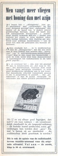
The advertisement is an oddity even to “Radio Bulletin” standards. The title translated reads “One can catch more flies with honey than with vinegar.” The advertisement starts by explaining how thoroughly disgusted the editors of “Radio Bulletin” were with the amoral and vile content of present (detective/western) picture novels. Possibly picture novels were something quite novel in post war Holland. Anyway, apparently the editors regarded the content as harmful for the young readers! As an antidote the editors decide on writing, a what they call “anti picture novel,” without the usual daggers, poison and stenguns, but nevertheless romantic enough so as to appeal to the hearts of youngsters. The advertisement ends by mentioning that the radio shops, “the munition arsenals” in this offence, heartily support this initiative by selling the booklet for 90 cents a piece.
 Today this would be equivalent to 7.40 Euro [1]. Quite a lot of money for such a thin booklet, especially considering that apart from the noble motives, obviously the main purpose of the book was to interest young people for electronics so that “the Muiderkring” could sell more “Radio Bulletins” and AMROH products.
The bill of materials for Rob’s receiver is 23.18 guilders (page 10 of Radio Bob). Today this would correspond to something like 190 Euro [1]! An enormous amount of money for a radio that you still had to make yourself, and that at best could only receive one or two stations. The fact that people were willing to pay that much money for so little shows how very special radio still was in those days.
The copy of “Radio Bob” in my possession has always been heavily damaged,
literally worn down by reading. The cover has been lost for as long as I can remember, so I had no idea how it looked like. However, some time ago I happened to visit the National Radio-Amateur museum “Museum Jan Corver” named after the Dutch radio pioneer Jan Corver. This is a delightful little museum located in Budel, a village just beneath Eindhoven [2]. It is a sort of grown out-of-hand hobby of Cor Moerman, who together with a group of volunteers runs the museum. Do not miss to visit the museum, if you are ever in the area, but mind, it is only opened the first and third Saturday every month. One of the most beautiful assets of the museum is a library with books and magazines related to radio amateurism. To my surprise and delight the library also happened to include a fully intact copy of “Radio Bob”. Cor Moerman was kind enough to lend it to me so that I was able to scan the cover.
| to top of page | back to homepage |
Thanks to the advertisement we know that “Radio Bob” was written by one or more of the editors of “De Muiderkring.” “De Muiderkring” published several magazines and a large number of publications and books for the booming do-it-yourself population in post-war Holland. In doing so, they extensively re-used their own material. Most projects were first published as a separate booklet, then appeared as an article in Radio Bulletin, and finally were collected in books like “Jongens Radio” (Boys Radio).
On page 4 of “Radio Bob” we have a view on the article in “Handig Bekeken” that catches Bob’s fascination. The title of the article reads “We gaan op vakantie en we nemen de radio mee!” (we are going on vacation and are taking the radio with us!). The subtitle reads “’n simple toestelletje dat het altijd doet” (a simple receiver which always works). It shows how fascinated the people in those days were by the idea of being able to listen to the radio where ever and when ever you wanted to. Obviously this is not so strange if we consider that during the war which had just ended, most people were not able to listen to the radio at all. It is therefore not surprising that the issues of “Radio Bulletin” in those years were literally swarmed with descriptions of small, battery powered, and portable radios.
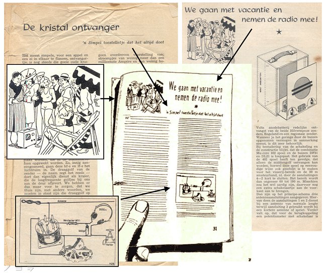
Figure 4 The editors of “De Muiderkring” heavily re-used their own material.
Even the layout of the page that Radio Bob is reading is composed of pictures
and headings from “Radio Bulletin” and “Jongens Radio” articles.
Click here or
on the picture to download a pdf of the complete article.
I have no idea if the article that Bob is reading was really published in “Handig Bekeken”. The only library that still has a copy of the complete 1948 issue is the central library of Amsterdam, and I haven’t been able to visit them. So, if there is anyone out there who owns an 1948 issue, please have a look! Anyway, as already mentioned the editors of “De Muiderkring” extensively re-used their own material, and I have been able to reconstruct almost the complete page that Bob is reading from clippings from either “Radio Bulletin”, or “Jongens Radio” fragments. Figure 4 shows how the title and the small picture depicting a group of people in full admiration over a radio in a beach setting, was copied from an article in one of the “Radio Bulletin” numbers from 1948. The sub-title and the circuit diagram were copied from the 1948 edition of “Jongens Radio”.
Figure 5 Illustration from “Radio Bob” and a picture from an article
in the april 1948 number of “Radio Bulletin”.
Click here or on the picture to read the complete article.
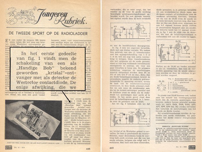
Figure 6 One of the few references to “Radio Bob” in an article in the 1949 december number.
Click here or on the picture to read the full article.
The only other reference to “Radio Bob” that I was able to find was in the December number of 1949, the same year “Radio Bob” was published. In “Jongeren Rubriek”, a column for youngsters, the working and construction of a simple battery tube receiver is discussed. The text explains that the circuit presented in Fig. 1 of the article consists of two parts: a crystal-set receiver followed by a simple low-frequency amplifier. The text refers to the first part as a circuit that had became known as “A Radio Bob crystal-set receiver”.
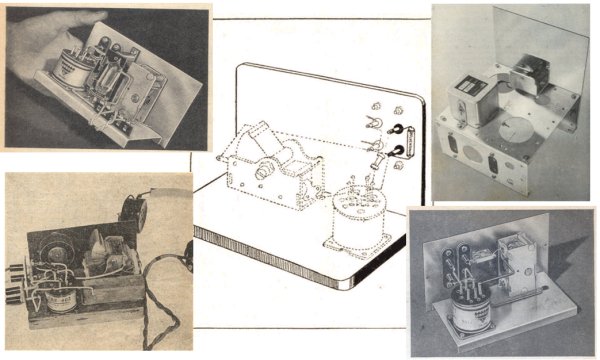
Figure 7 The way Bob’s receiver was constructed (center) was quite common for the period.
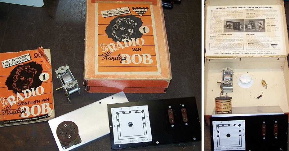
Figure 8 The “Radio Bob” crystal receiver was even sold as a (sober) kit!
I do not think that there is another device which arouses such intense nostalgic feelings among “older” electronic hobbyists in Holland, as does the legendary “Mu-CORE 402” coil. Inductors and coils have always been “difficult” components for amateurs. Most people do not possess an accurate RLC-meter, so that it is always a matter of hoping and praying that the inductor you make from a description is somewhere near the specifications required. In order to overcome this dilemma and so to address a larger hobbyist population, the designers from “de Muiderkring” designed a large number of universal inductors that could be used for different applications and frequency bands in a large number of designs. The inductors were fabricated by Amutronics and sold by AMROH, both sisters of the publishing company “de Muiderkring”.
Figure 9 The 402 was the backbone of many dozens of radio designs over a period of more than twenty years.
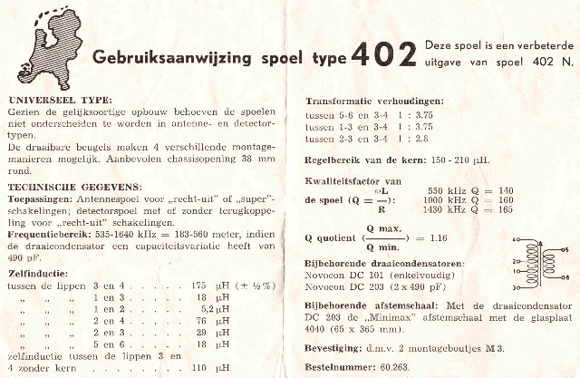
Figure 10 Datasheet of the Mu-CORE 402
The 402 was preceded by the 401. In the October issue of 1945 a receiver is published which uses the 401. According to O.C.A. van Lidth de Jeude, the 402 was first introduced in 1946 [16]. I have tried to find the first reference to the 402 in the 1946 edition of “Radio Bulletin”. The library of the Technical University in Delft has all the “Radio Bulletin” editions starting from 1933. Unfortunately, the 1946 edition is incomplete, and only contains the issues July December. The nice thing about internet is that sometimes people spontaneously contribute to my pages. Henk Stegeman was so kind to search his copy of the 1946 edition of Radio Bulletin, and actually found the first advertisement for the 402 in the May/June double number (Fig. 11 right). He also found an advertisement for the 401 in the February/March double number (Fig. 11 left). In the May/June number of Radio bulletin the first schematics with the 402 are given. In the July number of 1947 we find the first use of the 402 in a crystal-set receiver. This article will be discussed in the section dealing with the “Westector” detector.
|
|
Figure 11. Left, early advertisement for the 401 in the February/March double number of Radio Bulletin. Right, first advertisement for the 402 in the May/June double number. Click on the scans to view/download a high resolution version of the advertisments.
Both advertisements are very interesting because they reflect the shortage of goods in Holland the first year(s) after the war. Most radios had been confiscated by the Germans during the war, and buying a new radio set was not a priority for most people. The advertisement for the 401 explains that the 401 is a “temporarily compromise, designed to enable radio reception in this time of shortage.” In the first bullet it is explained that with a 401, an (old) variable capacitor and a diode radio reception using an old gramophone amplifier is possible. The advertisement for the 402 warns customers not to buy components of the “black market” but to buy the best components available (Amroh)!
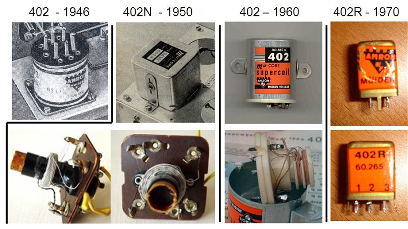
Figure 12 Three versions of the Mu-CORE 402. From left to right, the 1946 version of the 402, the 402-N introduced around 1950 and the 402 introduced around 1960 [19]. The Bottom row shows the interior of the 402-N [23] and the 1960 402 versions.
The round 402 coils were succeeded around 1950 by the 402-N in a rectangular (44x44 mm, 52 mm height) envelope (Fig. 12). In the beginning of the sixties, the 402-N in turn is replaced by a version in a cylindrical aluminum envelop (36 mm diameter, 42 mm height), again named the 402. The plastic coil frame in this version is made from Nylon which very quickly melts when wires are soldered to the leads, producing a very characteristic smell. Finally, in the seventies the 402-R is introduced. This version again has a rectangular envelope measuring 10.3 x 12.3 mm and a height of 18 mm. Unfortunately, I have never seen this version. If anyone owns one, please send me a picture so that I can complete Fig. 12. In the middle of the eighties, the demand for the coil had dropped to such a level, that production was stopped. This, after almost forty years of loyal service, inevitably meant the end for the 402 (order no. 60.265.000).
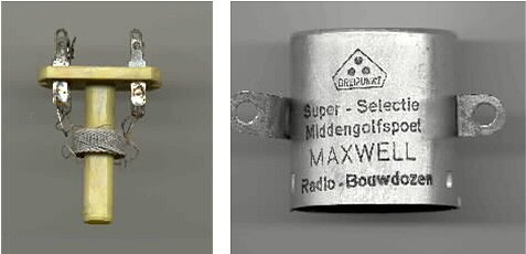
Figure 13 Imitation 402 made by the German company “Dreipunkt”
used in the “Pupil” receiver made by Maxwell [20].
In 1936 the Maxwell Company was founded by a radio-amateur. Its most important product was radio construction kits. One of the most favorite and famous models was “the Pupil”. It was a simple single tube (DL92/3S4 or DL91/1S4) battery receiver constructed around a Mu-CORE 402. The first kits used the square 402-N. It was later replaced by the round 402. When more and more kits were sold, the AMROH 402 was replaced by an imitation 402 probably fabricated in Germany by “Dreipunkt”. Figure 13 shows both the interior as well as the exterior of this imitation 402 [20]. The Maxwell company still exists today with many branches selling audio and television equipment in Holland.
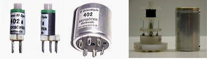
Figure 14 Imitation 402 inductors that still are being fabricated today (left and middle) [24]
and an homemade version constructed by Jan Rompelberg [25].
If you want to build one of the vintage circuits that uses a 402 design and you do not own an original 402 there are two options. Either you buy one from www.roehrentechnik.de, or you make one yourself. Figure 14 left and middle depict two 402 imitation coils available from “Roehrentechnik” suitable for PCB mounting at 5 Euro (left picture), or for chassis mounting at 9 Euro (middle picture)[24]. The right picture depicts an homemade version constructed by Jan Rompelberg.[25]
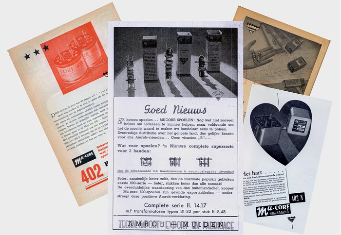
Figure 15 Several advertisements for the Mu-CORE 402 and other RF coils
taken from “Radio Bulletin” numbers from the period 1946-1949.
Figure 15 shows a collection of advertisements for the 402 and other coils taken from “Radio Bulletin”. The center advertisement is a bit of a curiosity. It was taken from the July number of 1946, exactly one year after the end of the war. It reads “Good News! … New coils, Mu-CORE coils, are arriving”. The text explains that new shipments of coils are being distributed evenly over the country. Not yet enough to satisfy the demand, but enough to justify a visit to local radio shop! For more than two generations, a home built receiver based on the Mu-CORE 402 was their first contact with electronics. I can very well imagine that for most people from that generation electronics today has lost its charm. It perhaps explains why today prizes up to 100 euro are paid for second hand 402 coils.
| to top of page | back to homepage |
In the circuit diagram on page 16 and in the drawing on page 26 of “Radio Bob” we read that Bob uses a “Westector” as detector. The Westector was developed around 1930, and it served as a detector in applications where a diode tube detector was undesirable until 1947 when it was replaced by germanium diodes.
The detection of radio waves in the early days of radio was not a trivial matter. In the first experiments the presence of radio waves was detected by the occurrence of tiny sparks in the resonator, which were barely visible even when it was located in a dark room. The coherer, invented by Edouard Branly in 1890 was the first usable device which allowed for detection of Morse code signals from spark transmitters. The coherer from Branly was based on the observation from Munch of Rosenhold in 1838 that the resistance of iron filing drastically decreased when subjected to an electrical discharge. Branly’s coherer consisted of a sealed glass tube with two electrodes filled with iron filing [15]. Under influence of resonances in the tank circuit, the resistance drop of the iron filing was enough to switch on a relay or buzzer. The coherer could be reset by gently tapping it.
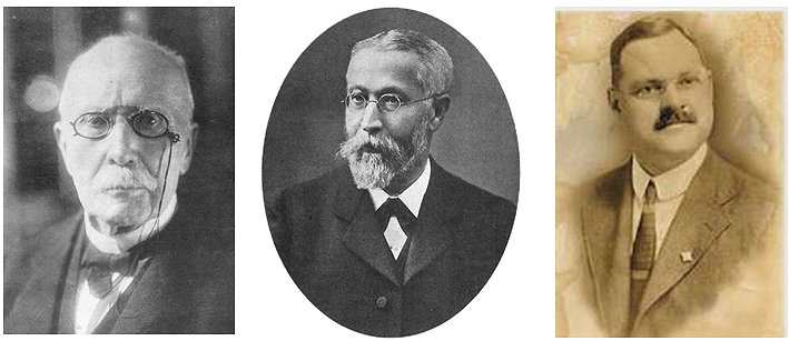
Figure 16 From left to right: G.W. Pickard, K.F. Braun and E. Branly.
Already in 1874, Karl Ferdinand Braun had discovered that contacts to metal-sulfide compounds conducted an electrical current in one direction much better than in the other direction. It took however until the summer of 1902 until G.W. Pickard discovered how a rectifying steel-carbon contact could be used to detect signals from spark transmitters. Interested in this phenomenon, Pickard spent ten years on finding the most optimal combination of materials. In total Pickard tested more than 30.000 materials combinations! Some of the very sensitive combinations Pickard found were: magnetite-copper, silicon-steel. Also metal oxides such as zinc- and lead-oxide as well as galena (lead-sulfide) were found to be very sensitive.
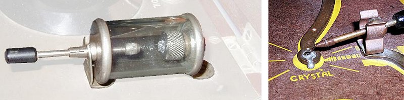
Figure 17 Two “cat’s whisker” detector examples
Pickard’s work resulted in the first usable detector device, the “Cat’s whisker”. It consisted of a small crystal, usually galena, in a fixture that was contacted by a phosphor bronze wire, the whisker [7]. The whisker was probed over the surface of the crystal until “a sensitive spot” was found. The arrangement was however very critical and the slightest shock or movement could ruin the reception. Even without any movement of the detector, a sensitive spot would wear down over time so that a new sensitive spot had to be found. The simplicity of the cat’s whisker, and its low price undoubtedly contributed to the popularization of radio reception by amateurs in the period 1910-1920. Gradually however, the crystal detector was replaced by the much more sensitive and stable vacuum diode. The Second World War however caused a revival of the cat’s whisker. In the occupied countries like Holland, people had to hand over their radios to the Germans. On top of that near the end of the war there was often no electricity and batteries were not available. The scarcity made people ingenious and people fabricated detectors from materials they could lay their hands on. I once read a description of a crystal detector from made from lead pencils and steel razor blades [6].
In the 1930s industrial researchers became intrigued by a new rectifying device: the copper-oxide rectifier. At the beginning of the 1920s Lars Grondahl of the Union Switch and Signal Company in the U.S. was studying failure mechanisms in switch contacts and he became curious as to why tarnished copper behaves as it does. He and a colleague, Paul Geiger, discovered that cuprous oxide is a semiconductor (of course the concept of semiconducting materials was unknown at that time). By around 1922 they had developed a rectifier based on disks of copper abutting disks of cuprous oxide [3,4]. In contrast to the point contact devices that preceded it, these are large-area rectifiers. As a result, these copper-disk devices found use as high-power rectifiers, the first solid-state devices capable of doing so. Bell System adopted these devices to act as modulators for carrier based telephony
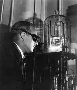 One of the researchers at Bell Labs trying to understand the working and behavior of copper-oxide rectifiers was Walter Brattain, who later on invented the transistor together with Bardeen and Shockley. “The difficulty in this period was that copper-oxide is such a messy type of structure-sensitive thing,” he later recalled. And only certain kinds of copper (such as copper that had come from specific mines
In Chile) seemed to work well [5]. The picture on the left shown Brattain evaporating silver contacts on copper-oxide rectifiers. There was great confusion in the scientific literature about exactly where this one-way rectification process was happening – whether it came in the copper-oxide layer itself or occurred at its depper interface with the copper metal. After working over a year on this question, Brattain and his co-worker Becker finally satisfied themselves that the process took place at the boundary between the two layers.
One of the researchers at Bell Labs trying to understand the working and behavior of copper-oxide rectifiers was Walter Brattain, who later on invented the transistor together with Bardeen and Shockley. “The difficulty in this period was that copper-oxide is such a messy type of structure-sensitive thing,” he later recalled. And only certain kinds of copper (such as copper that had come from specific mines
In Chile) seemed to work well [5]. The picture on the left shown Brattain evaporating silver contacts on copper-oxide rectifiers. There was great confusion in the scientific literature about exactly where this one-way rectification process was happening – whether it came in the copper-oxide layer itself or occurred at its depper interface with the copper metal. After working over a year on this question, Brattain and his co-worker Becker finally satisfied themselves that the process took place at the boundary between the two layers.
The confusion on its exact working did not prevent Bell Labs from forging ahead with the production of copper-oxide rectifiers, called “varistors,” on an industrial scale. Becker and Brattain worked on this effort in the mid-1930s, experimenting on different methods of applying electrical contacts to the oxide surface. Once they had succeeded, they built a large vacuum chamber in which gold or silver leads were deposited on the back sides of the oxide layer. Bell Labs produced more than 10,000 varistors before the process was transferred to the Western Electric plant in nearby Kearny, New Jersey, for full scale production. Around 1933 a series of copper-oxide rectifiers, designed especially for radio detection was introduced under the name “Westector”. I have no idea when, or even if the Westector was introduced in Holland before the War (1940).
Searching through the archives of the Philips Research Laboratory in Eindhoven, I found an interesting research report describing measurements on a number of “Westector” devices. Philips was at that time already one of the leading radio tube manufacturers in Europe, so obviously they closely watched what the competition was doing. The report is dated April 1933, so that we can safely assume that the Westectors were introduced on the market only shortly before this time.
| type | maximum voltage | maximum current | price in English shilling |
| WS 4 half wave | 24 V | 0.25 mA | 7s/6p |
| WS 6 half wave | 36 V | 0.25 mA | 7s/6p |
| WM 24 full wave | 24 V | 0.5 mA | 10s/- |
| WM 36 full wave | 36 V | 0.5 mA | 10s/- |
In the report four Westector devices were evaluated (Table above). The W4 and WM24 devices each consisted of 4 copper disks in series, on one side provided with copper-oxide, separated by a small disk made out of a soft metal, presumably a lead-compound. The pile of disks is pushed together by a small spring. The W6 and WM26 had the same construction, but contained 6 copper disks in series. From the difference is in breakdown voltage between the W4/WM24 and W6/W26 devices (resp. 24V and 36V), we may deduce that each individual disk had a breakdown voltage of about 6V.
The research report also cites some interesting quotes from a datasheet, or “pamphlet” as it is called in the report that accompanied the Westectors:
“A special development of the Westinghouse Metal Rectifiers, the Westector, in intended for rectification of HF currents. In other words it is a metal detector which will replace the diode or duo-diode (or perform the detection function of a triode valve, without giving amplification).”
A full transcript of the quotes from the datasheet is given in Appendix A.
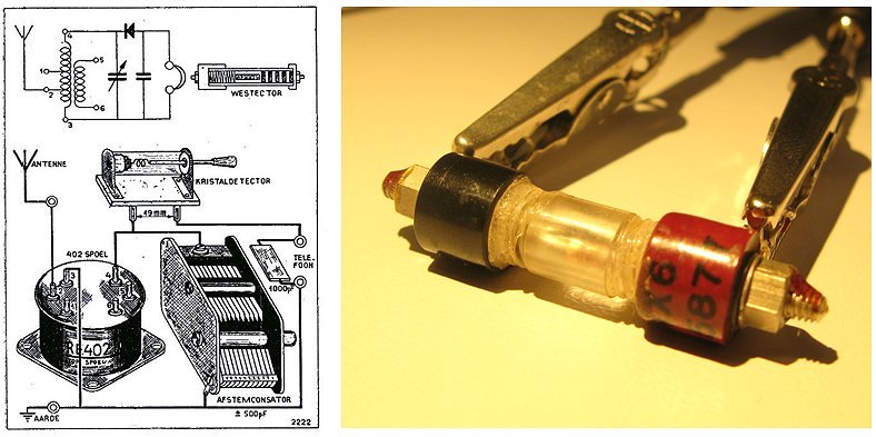
Figure 18 The first crystal-set receiver published by “Radio Bulletin” in the July number of 1946
promoted the brand new Mu-CORE 402 (left). As an alternative to a “cat’s whisker” detector
the article suggest the WX6 “Westector”. The picture on the right shows the wx6 “under test”.
The detector used by “Radio Bob” is a WX1. Presumably this device contains only 1 copper disk. In the July 1947 number of “Radio Bulletin” we find the first description of a crystal-set receiver using the then brand-new Mu-Core 402 coil (Fig. 17). In the article a “cat’s whisker” detector is used, but at the end it mentions that also a metal detector can be used which does not require any adjustments. No type number is used, but the article suggests that the best results are obtained when the Westector is opened, and all but one of the copper disks is removed! The Dutch National Radio-Amateur museum “Museum Jan Corver”, fortunately had a WX6 device in its collection, and Cor Moerman was kind enough to lent it to me so that I could photograph and measure it [1]!. At Philips Research we measured the IV characteristics using a Keithly 4200 state-of-the-art semiconductor parameter analyzer (Fig. 19). Surprisingly, the device still functions! In Fig. 19 (left) the WX6 is compared with a germanium diode I had lying around. In forward mode the current is about an order of magnitude lower than the current in the germanium diode. Possibly this is caused by some oxidization of the contacts of the disks during the past 80 years! Also surprisingly the reverse current of the Westector is much lower than the reverse current of the germanium diode.
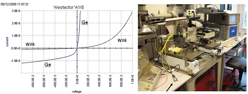
Figure 19 IV-characteristic of the vintage WX6 compared to a Germanium diode (left).
A curious combination, A state-of-the-art semiconductor measurement set-up was used
to characterize one of the first solid-state semiconductor devices (right).
It is understandable that people during the war considered the cat’s whisker to be a “poor man’s” detector. At the beginning of the Second World War in Holland, the “cat’s whisker” was already an almost obsolete piece of technology; a kid’s toy. Nevertheless, after most people had handed over their radios to the Germans, and when radio parts such as tubes and batteries were no longer available, many people built crystal-set receivers using a “cat’s whisker” or a comparable homebrew device. These devices, unreliable as they were, must have caused an enormous amount of frustration and irritation. When the war finally ended, most people not surprisingly though that they had now seen the last of these crystal-detector devices, and they were only too glad to move on to radio tubes and the newly developed “Westectors”.
What people were unaware of was that the development of radar during the war in the U.S., in particular the development of radar detectors, had stimulated an enormous development in crystal detectors. Although microwave sources were readily available after the discovery of the magnetron tube by the British, the detection of micro-waves was a completely different matter. During his research into microwave propagation and microwave signals, George Southworth of Bell Labs was frustrated over the poor performance of vacuum tube detectors at microwave frequencies. Also copper-oxide rectifiers were of no use at those frequencies. Southworth decided to test some ancient “cat’s whisker” detectors. He reasoned that the tiny point contact might have a corresponding low capacitance, and thereby enable operation at the higher frequencies desired. A trip to the surplus shops of New York’s Cortlandt Alley was all it took to find some old “cat’s whisker” detectors. After cleaning up the dusty relics, he discovered to his relief and delight that they indeed worked extremely well [5].
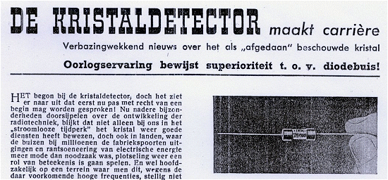
Figure 20 The first news on the developments in solid-state diodes during the war in the July 1946 number.
Click here oron the picture to download a pdf of the complete article.
Encouraged by these results Bell Labs and several other research institutes embarked on research programs on solid-state rectifiers based on silicon and later germanium. Tedious researched unveiled one-by-one the mysteries of these semiconductors, eventually resulting in reliable point-contact diodes. The people in Holland, obviously totally unaware of these developments, read to their surprise an article in the July 1946 number of “Radio Bulletin” entitled, “The career of the crystal-detector!”. The subtitles translate, “surprising news about the crystal that was considered to be obsolete. War time experience proves superiority compared to the vacuum diode.” Eventually all this research led to the invention of the transistor in December 1947 by Bardeen, Brattain and Shockley.
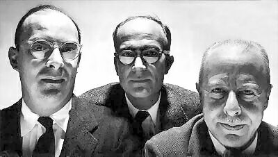
Figure 21 Bardeen, Shockley and Brattain (left-to-right)
| to top of page | back to homepage |
On the 6th of November 1919, the Dutch radio pioneer Steringa Idzerda, transmits a “Soirée Musicale” from his radio production plant in Den Haag. It is a world premiere: it is the first public radio broadcast in the world that was preceded by an announcement in the newspapers! In Holland this triggered an explosive growth of the number of amateur enthusiast who all wanted to built their own radio. This development didn’t pass unnoticed by Georg Kauderer, the son of a toll-collector and lock-keeper in Muiden. Georg had served for a few years in the navy as a wireless operator, and had worked a few years in the U.S. Together with his brother Jan, he founds the “AMerican RadiO House” trading company. This small company sells radio parts imported mainly from the U.S. to shops and individuals around Amsterdam [16].
Their business prospers, and in 1929 they decide to publish a brochure with their products. The brochure is called “AMROH Bulletin”, it contains pictures and descriptions of gramophones, loudspeakers, filament resistors etc. Several numbers appear, and in 1932 “AMROH Bulletin” starts to appear as a periodical to which people can subscribe for one guilder per year for twelve numbers. The magazine now apart from advertisements and product information also contains schematics and construction diagrams.
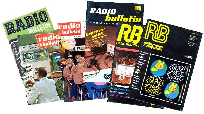
Figure 22 The face of “Radio Bulletin” through the years.
From left to right 1949, 1967 (both in 16x24 cm format), 1970, 1975, 1977, 1982 (all in 19x27 cm format)
By that time the name “AMerican RadiO House” had been abbreviated to AMROH. AMROH is a daughter of the holding company “Geo C.F. Kauderer N.V.”. In 1936 the publishing company “De Muiderkring” is added as a daughter to the holding. “De Muiderkring” publishes the “Radio Bulletin” magazine and other publications with the purpose to promote the products from sister company. In 1935 the sister company “Amutronics N.V.” is added to the holding. Amutronics manufactures electronic parts, mainly transformers and RF-coils (e.g. the famous MuCore 402!) which are then distributed and sold by AMROH. The combination of the three companies is ideal. Amutronics manufactures, AMROH distributes and sells, and “De Muiderkring” promotes all these products though periodicals such as “AMROH Bulletin”
In 1937 the name “AMROH Bulletin” is changed to the more neutral “Radio Bulletin” and in 1940 also other companies and firms are allowed to advertise their products in the magazine. “De Muiderkring” also published a number of other magazines (e.g. “Hobby Bulletin”), numerous building descriptions (e.g. Figure 23), books etc. Most circuits and projects were extensively re-used, and first appeared in separate building descriptions subsequently found a place in “Radio Bulletin” and finally were collected in books like “Jongens Radio” (“Boys Radio”).
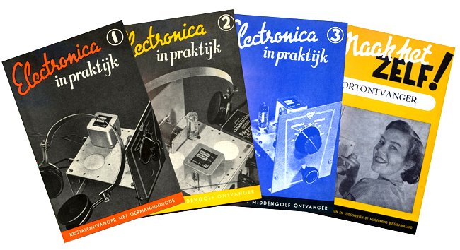
Figure 23 “Electronics in Practice” and “Make it yourself”, examples of complete building descriptions
published by “De Muiderkring”. Click
here or on the picture to view the booklets.
“Radio Bulletin” undoubtedly was a beacon for many generations of Radio enthusiasts with a peak around the post-war period. When the war was over, the Germans had left behind them an impoverished and empty country. People were in want of everything and spend the little money they earned on the first necessities of life. At the same time they learned about the fantastic new developments that had occurred in the U.S. during the war. The combination of the two caused an explosive growth in amateurs who build their own radio equipment. However, in the eighties the market for homemade equipment gradually vanished because most people simple prefered to buy their equipment. “Radio Bulletin” additionally had great difficulties in making the move from the analog radio/amplifier area to the digital/computer age. In 1985 the name of the magazine was changed to “RB Elektronica Computers”, but in 1987 it was changed back again to “RB Electronica Magazine”. Finally on the 23 of April 2002, after 78 years, a bankruptcy is inevitable.
| to top of page | back to homepage |
The story of “Radio Bob” is what we could call, a radio detective story - a story in which a radio
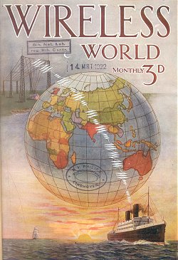 played a important role in committing, preventing or solving of a crime. It was however by no means the first radio detective story. Browsing through a volume of the magazine “Wireless World” from 1922 (picture left), I found what is perhaps the first radio detective story ever written! The story which appeared in the March issue is titled, “Code”. Remember that in 1922 radio was still in its infancy. The first publically announced broadcast took place only a few years earlier in Holland in 1919 when the radio station from Dutch radio pioneer Staringa produced a musical evening soiree. It is now hard to imagine, but a story like Code must have almost been science fiction to the readers of “Wireless World” in 1922.
The story is about two friends and radio-enthusiasts, Roger Blake and Jack Faucet. Jack Faucet is young doctor with an extensive practice in a small isolated country down. In his scarce spare time he had rigged up a small receiving set. Jack and Roger had both been signalers in the Officers Training Corps. Their they had rapidly fallen under the fascination of the “dot-dash-dot”. Also at university they had many a pleasant evening practicing with a dummy-key or buzzer. At a certain evening both friends are searching “the wavelengths” on the off-chance of picking up any stray message that might be audible, when they take down a ciphered message. Blake, who used to be “rather a nut” at deciphering codes in his younger days is able to crack the code after a few attempts. It appears to be a message from some thieves which are planning a jewelry theft. They quickly warn the police, and as may be expected, the theft is prevented resulting in the inevitable “happy end”.
The story itself is nothing special and it is even a bit childish. It derives its charm from the fact that it is one of the first detective stories in which radio plays a central role, more than 25 years before “Radio Bob” was written. If anybody out there knows of similar early “radio detective stories,” please let me know!
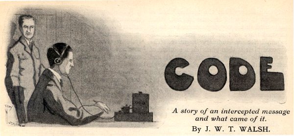
Figure 24 John Faucet (sitting) and Roger Blake (standing) in “Code”.
Click here or on the picture to read the full story.
| to top of page | back to homepage |
Making your own copy of “Radio Bob” is easy.
Both a
Dutch version
or an
English version
are available here in pdf format. Take care that during printing the backside of the pages are orientated in such a way to allow normal turning of pages. This may require adjusting one of the printer setting. How this can be done exactly depends on the printer. Figure 25 gives an example for two printers. When the print window opens click on preferences. In the preferences window tick either “Flip Pages Up” box (left) or select “Flip on Short Edge” (right).
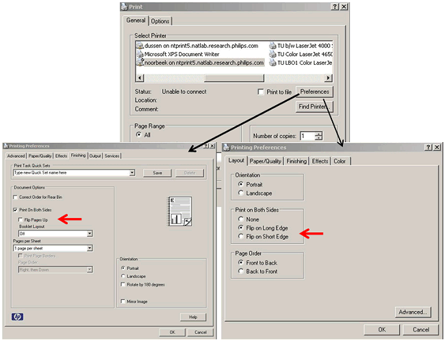
Figure 25. Two examples showing how to flip the back-side of the printed pages if needed.
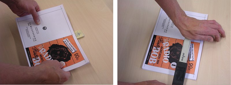
Position centerline of the printout on a pencil eraser and push two staples through the printout
at the location of the dashed line into the eraser.
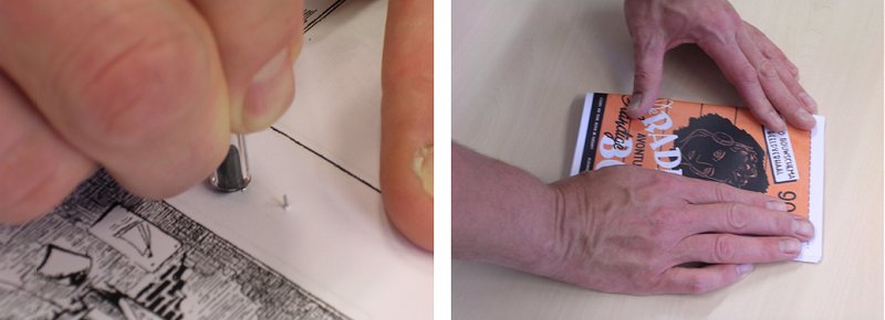
Remove the eraser and fold the sharp edges of the staples inward with a blunt object
e.g. the back of a pencil. Fold the booklet.
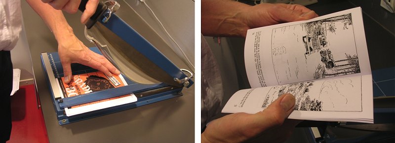
Figure 26. Trim the edges of the booklet using the dashed lines as a guide.
| to top of page | back to homepage |
| to top of page | back to homepage |
| to top of page | back to homepage |
An article about “Handige Bob” in the “Radio Historisch Tijdschrift” the periodical of the Dutch Society for the History of Radio (NVHR).