|
Contents:
|
|
|
Contents:
|
|
|
The making of the E1T |
|
The nixie tube ¢ introduced by Burroughs in 1954 ¢ originally suffered from one drawback: it required a driver transistor with a reasonably high breakdown voltage. However, in the early days of the transistor, these devices were however not generally available. Consequently, researchers at Philips saw a market opportunity for an indicator tube that could be driven directly by a low-voltage transistor circuit. The Z550M - or ZM1050 as it was later rechristened ¢ was the result. It basically consists of ten individual neon tubes in one envelope. Each neon tube is provided with a special starter electrode allowing the tube to be driven by a low voltage, low power signal.
The Z550M has a number of things in common with another remarkable scaler tube that was also developed at Philips research a decade earlier, the E1T. One important commonality is that with both tubes it is possible to construct a self-counting circuit, without the need for additional active components. The E1T inherently is a scaling device, while the Z550M basically is only an indicator devices which can be configured as a ring counter circuit using only capacitors, resistors and diodes. Another thing both tubes have in common was that neither of them became a convincing commercial success, in fact both tubes never made it beyond the pilot production phase. The E1T - although brilliant in conception - was soon outdated because of the advent of transistorized counting circuits. The Z550M quickly became obsolete because of the development of high voltage transistors (the BSX21 in Europe) which allowed nixie tubes to be directly driven from transistorized circuits.
One of the advantages of working at Philips Research is that it is for me relatively easy to access old research reports and lab note-books. While researching the history of the E1T tube, I came across some research reports related to the Z550M. This lead allowed me to unravel the history of this remarkable tube. Philips has a very rich tradition in gas discharge research. The fluorescent tube, the sodium lamp, sputter cleaning of cathodes, metal gettering and the Penning gas mixture are but a few of the many inventions and innovations that resulted from this research. On this page you can read an overview of this history and a reconstruction of the invention and development of the Z550M.
| to top of page | back to homepage |
In 1913 Philips was one of the largest incandescent lamp manufacturers in Europe, and the largest private employer in Holland. Nevertheless, within a time frame of three years, Philips had twice been taken completely by surprise by two important innovations by their competitor General Electric, namely the pulled tungsten wire filament and the gas filled incandescent lamp. Gerard and Anton Philips realized that what their company was lacking, was a research department that could look into the fundamental aspects of electric light sources and their properties. So in 1914 the brilliant young scientist Gilles Holst was hired to set up a Research Lab. (Read more about the history of Philips and of Philips Research on my öThe making of the E1Tö page.)
Almost from the inauguration of the Philips Research Lab, Holst felt that it was already too late to carry out fundamental research on incandescent lamps [1]. The time was ripe to try and develop a new source of electrical light, the discharge tube. Discharge tubes were still something very new and fancy in 1914. It was not until 1908 that George Claude was able to produce neon gas in reasonable quantities. Philips, with its own gas factory, was soon able to produce neon (and other rare gases) by itself, and in 1921 put a glow discharge lamp on the market, they could however not compete with incandescent lamps. Also the glow discharge itself was a phenomenon which was still poorly understood at that time. Philips Research would play a very important role in developing the understanding and applications of glow discharge lamps.
Holst and his colleague Oosterhuis had shown that the striking voltage of neon depended on the material of which the cathode was made, being low when the material had a low work function (e.g. sodium or magnesium) and high when the work function was high (e.g. silver of graphite). They therefore assumed that electrons were liberated by positive ions striking the
cathode, rather than by collisions with gas atoms, as many scientists (J.W. Townsend) believed. Their assumption was proven right by the discovery of a series of black and luminous striations near the cathode ¢ which became known as the Holst and Oosterhuis sheats - which showed that all electrons must lose their energy at the same distance from the cathode, which only makes sense if they originated from the cathode.
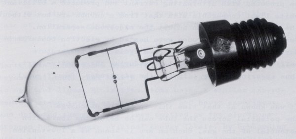
Figure 1. The AC Tungsten arc lamp invented by Holst and Oosterhuis
Holst and Oosterhuis also investigated other ways in which the cathode affected the discharge. They found that if the cathode temperature was low, the cathode was sputtered by the bombardment of positive ions. However, if the cathode temperature was high, the thermionic emission of electrons would form a charged double layer in the vicinity of the cathode that would prevent the ions from reaching the cathode. This led to what was known as the tungsten arc-lamp. It consisted of two small spherical tungsten electrodes which were mounted in such a way that they were more or less thermally isolated from the supporting frame (Fig. 1). The arc-lamp was operated from an AC voltage. When the tube is switched on, the spheres are heated to such a temperature that they became white hot and started to emit electrons. From then on the electrode would be heated during the positive phase of the AC voltage, while during the negative phase sputtering of the electrode was prevented because of the charged double layer.
BohrÆs atom theory was published in 1913, so it was still quite new at that time. In 1914 James Frank and Gustav Hertz had already published experiments which indicated the validity of BohrÆs model from observations in gas discharges. Also Holst and Oosterhuis were fascinated by the idea of linking BohrÆs model to the phenomena of gas discharges, especially the spectral line pattern. They carried out some initial experiments which were inconclusive, but soon found that, since the lab was growing quickly in the post war period (WW I), their managerial tasks consumed too much time to be deeply engaged in scientific work as well.
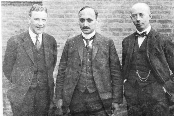
Figure 2. Holst, James Frank and Gustav Hertz around 1924
In 1920, Holst was able to persuade Gustav Hertz to join the Philips Research Lab (Fig. 2). Amongst many other things, Hertz performed a beautiful experiment which established beyond all doubt that BohrÆs electron states were linked to spectral lines. By bombarding atoms with electrons of different energies, he demonstrated that all the lines requiring a specific amount of excitation energy were absent from the spectrum until the electron energy exceeded a threshold value. To complete the neon spectrum, Hertz needed to identify two lines in the far UV that had not been observed before on account of the difficulties in detecting UV at that wavelength because of the absorption by both glass and air. So Hertz, with the help of J.H. Abbink constructed a vacuum spectrograph in which the gas discharge , the grating and the photographic plate were all placed in one vacuum envelope. In this way in 1925 he observed two lines exactly where he predicted them to be. Later H.B. Dorgelo used the same instrument to observe the UV spectra of other rare gases.
Despite the fundamental research carried out by Holst, Oosterhuis and Hertz, discharge tubes were still a far way from being a practical product. They produced anything but white light and their efficiency was low because spectral lines outside of the visible spectrum were wasted. Holst had the idea that perhaps their efficiency could be improved if the invisible part of the spectrum was used to make suitable materials fluoresce. So when Gerard Zwikker and Willem de Groot joined Philips Research in 1923, he immediately set them to make a fluorescent tube. Zwikker later recalled how he was walking with de Groot in ōde Rechtestraatö in Eindhoven when they happened to look into the window of a boutique:
| In the window there were a number of objects made from uranium glass. We entered the shop and bought everything we could find that was made of uranium glass. Fortunately, we had some money in our pockets which we got back afterwards from the company. We brought the vases and ash trays to Esseling a glass blower who smashed them into pieces and made from them a long uranium glass tube - several meters in length - in which de Groot produced a mercury discharge. This tube served for many years as a green line below the red Philips letters on the light tower. De GrootÆs tube was made early 1923 and he finished the job in only fourteen days. We were astonished by the amount of light it emitted. |
The most significant contributions from Philips Research to the fundamental science of gas discharges were made by F.M. Penning. Penning studied Physics in Leiden under the famous Kamerlingh Onnes. He joined Philips research in 1924 and began working almost exclusively on electrical discharges. A complete summary of all his work and experiments would be too exhaustive for this page. We have already seen how his measurements of breakdown potentials resulted in a cathode cleaning technique known as ōcathode sputteringö and a gas cleaning technique based on metal gettering. I will limit myself here to two other examples of his work which are relevant for nixie and other indicator tubes.
In one experiment, Penning constructed a, what we today call relaxation oscillator, by placing a capacitor parallel to a discharge tube, and a resistor in series with both. As we know this produces a saw-tooth like signal. Penning was able to measure the striking and maintaining voltages under these dynamic conditions. This was not an easy task before the availability of oscilloscopes! He found that the striking voltage could be considerably lower as compared to the DC case. He explained this result by the presence of electrons and ions that had not yet recombined.
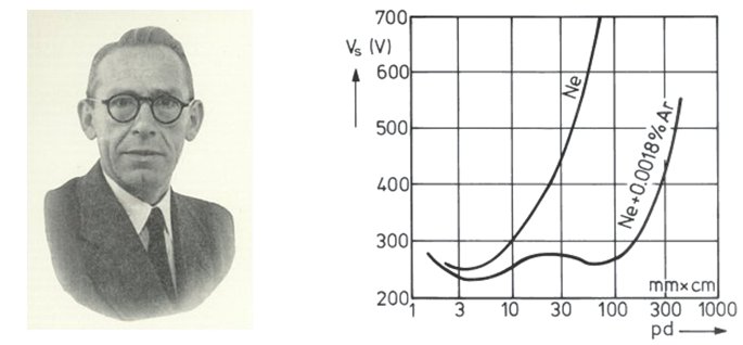
Figure 3. On the left, Frank Michel Penning (1984-1953)
On the right a Paschen Curve, or striking voltage versus the product of gas pressure and inter-electrode distance,
for pure neon and a ōpenning gasö of neon + 0.0018% argon.
In 1927 Penning (Fig. 3 left) measured the breakdown voltage of a neon discharge as a function of pressure and distance between the electrodes. The result is known as the Paschen Curve, after Paschen who had discovered that the breakdown voltage is a function of the product of gas pressure and electrode distance. Penning found that his results were only consistent if he used extremely pure neon. Minute traces of other gases, such as argon, lowered the breakdown voltage considerably (Fig. 3 right). Penning knew about the work of Dorgelo on metastable states. Metastable states in Neon had been discovered by Meissner in 1925. These are energy states well above ground state, from which all transitions to lower states are forbidden. Atoms in these metastable states generally return to ground state by either going through a higher energy state or by a collision. As a result metastable states can have lifetimes in the order of a millisecond. Penning proved that what was happening in his gas mixtures was that before the electrons have sufficient energy to ionize the neon, they can excite neon atoms, and these excited atoms can pass into metastable states. Because of their relatively long lifetime, there is a high probability of collision with one of the impurity atoms. Argon has an ionization potential below the energy of metastable neon, so argon atoms will ionize leading to the initiation of the discharge. Such a gas mixture became known as a Penning Gas. It can be used to lower the breakdown voltage of a discharge tube, or to make the breakdown less dependent on the inter-electrode distance.
Figure 4. On the left an early sodium lamp, lamps of this type were used to light the worldÆs first road to be lighted with
sodium lamps between Beek and Geleen in the province of Limburg. On the right an early high pressure mercury lamp
type SP500, an early commercial version of BolÆs water cooled lamp, note the water connections on the left.
To conclude, this section we can add that in this period also the sodium lamp and the high pressure mercury lamps were developed (Fig. 4). The former found application in street lighting, while the latter, due itÆs extremely high brightness first was used in projectors. These first lamps were water cooled. In applications such as street lighting were water cooling was not possible, a lamp was developed which operated at a pressure of 5 to 10 atmosphere.
| to top of page | back to homepage |
In this section we will discuss the technical aspects of the Z550M, in the next sections we will have a look at the people who invented it and turned it into a product. The Z550M is best introduced by quoting the introductory paragraph of section 10.3 from ōThe Z550M Indicator Tubeö by J.B. Dance [2]:
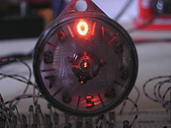
| The Mullard/Philips Z550M is a unique tube which has been developed to satisfy the need for a decade indicator tube which can operate directly from the low voltage electrical readout provided by transistor scalers (counters). It requires an input signal of about 5V at a current of about 50 µA. The form of the display is different from that of other indicator tubes. Ten figures are cut in the anode in the shape of the digits to be indicated; they are arranged in a circle, each digit being 3 mm in height. A gas discharge takes place behind one of the digits so that red light from the discharge shines through the cut away portion of the anode in the form of the digit to be indicated. The display can be quite bright, since the control circuit does not supply the power to the main discharge. |
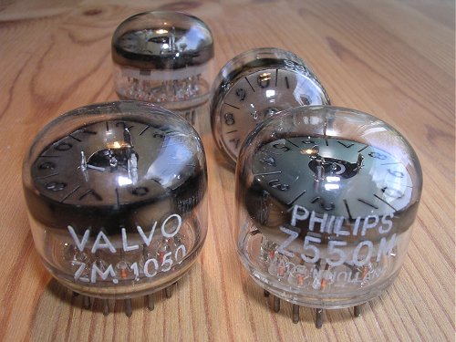
Figure 5. The ZM1050/Z550M with labels Philips and VALVO.
In fact all ZM1050s were made at the main tube production side of Philips
at the ōEmmasingelö in Eindhoven, the Netherlands (see Epiloque).
The working of the ZM1050 resembles the working of the circuit discussed on my ring counter page. The basic idea is that ten glow-discharge tubes, with very matching characteristics, are integrated into one envelope. The tube is fed with a half-sinewave voltage in such a way that the small additional voltage from a transistor preferentially ignites one of the ten glow-discharges. Next, the common anode voltage now drops so that none of the other glow-discharges strike. A special provision has been made so that the striking of each discharge is initiated by a separate ōstarter anodeö which is driven by the transistor and requires only a very small current. This auxiliary discharge is then transferred to the main discharge at a much higher current level. A more exact and complete explanation of the working can be found in an article by one of the inventors, Theo Botden, in ōElectronic Applicationsö [3]:
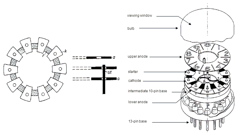
Figure 6 shows the arrangement of the electrodes of the Type Z550M (ZM1050) indicator tube. The ten approximately trapezoidal plates k act as emissive cathodes. They are mounted on a ring-shaped conducting support r, the shaded sections of which are coated with a material having a high work function compared with the cathodes k to reduce their electronic emission. A short distance above and below the cathodes annular anodes a are mounted. Ten wire electrodes st, the starters, protrude through holes in the lower anode ring and in each of the cathode sections. In the upper anode ring the figures from 0 to 9 are cut out, so that when a glow discharge is initiated by means of one of the starters, the figure facing the corresponding cathode clearly stands out. Figure 7 shows an exploded view of the electrode system. The emissive cathode sections have been ōsputteredö during the manufacturing process to obtain clean cathode surface, whilst the sputtered material settled on the glass envelope prevents contamination of the gas, and thus ensures stable operation. The tube is filled with neon to which a small percentage of argon is added.
The tube is fed with an unsmoothed rectified voltage (see Fig. 8), so that with half-wave rectification, the supply voltage rises to a maximum and drops to zero again once in every mains cycle. When the supply voltage reaches a certain value, a glow discharge is initiated which extinguishes again as soon as this voltage drops below the maintaining value. The glow discharge is thus obviously ignited and extinguished twice per cycle when full-wave rectification is employed. As can be seen from Fig. 8, the starters are at anode potential as long as there is no discharge. However, as the distance between each cathode and its associated starter is much smaller than that between the cathode and the anodes, a discharge between cathode and starter will be initiated before the supply voltage has risen to the value at which a discharge between the cathode and anode is established. When, therefore, the supply voltage progressively rises from zero, the first effect will be the initiation of an auxiliary discharge between the cathodes and its starter. The operation of the Type Z550M (ZM1050) indicator tube is based on the fact that an auxiliary discharge between one of the cathodes and its starters reduces the required anode ignition voltage Vaign between this cathode and the anode to such an extent that the main discharge is also established at this cathode. It thus suffices to make a provision for an auxiliary discharge to be established at the desired cathode to ensure that the main discharge occurs at the corresponding figure. This main discharge causes the anode potential to drop suddenly to the maintaining voltage Vm which is below the lowest ignition voltage at any other cathode, so that no discharge can be initiated elsewhere. In other words, ōfirst come, first servedö applies; at any rate as far as that particular cycle of the supply voltage is concerned.
The dependence of Vaign on the starter current Ist is plotted in Fig. 9 for one of the starter-cathode positions. It is seen that when the starter is disconnected (Ist=0) the voltage required for initiating the main discharge is approximately 135V, but at a starter current of, say, Ist=10µA, this voltage is reduced to approximately 105V, which is mainly due to positive and negative charge carriers diffusing from the auxiliary discharge to the space between this cathode and the anode. If therefore, at a particular cathode, a starter current of this value is made to flow, the main discharge from that cathode is initiated in advance of that from the other cathodes by an amount corresponding roughly to the time the supply voltage takes to rise from 105V to 135V.
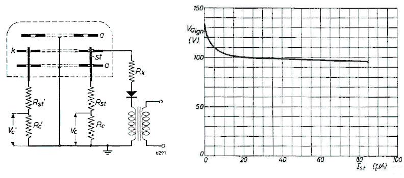
The cathode at which the auxiliary discharge is initiated can be selected by raising the voltage at the desired starter slightly above that of the others. This may be done by applying a small positive control voltage Ve across resistor Rc. The corresponding starter then reaches the ignition voltage prior to the others, so that the discharge occurs at the desired position. If the control voltage Vc is transferred to another starter the re-ignition will take place at the new starter-cathode combination at the next (half) cycle, and so on. The reason for employing an unsmoothed supply voltage will now be clear, namely that, in order to transfer the discharge from one cathode to another, the discharge must first be extinguished by reduction of the supply voltage to below the maintaining value, after which it must rise again gradually so that the desired starter can initiate the next discharge. The control voltage, that is to say the additional impulse required to initiate the auxiliary discharge at a particular cathode, may be very much smaller than the maintaining voltage, since the total starter voltage need only be slightly higher than the voltages at the other starters. A control voltage of only 5V is all that is required with the ZM550, provided the supply voltage meets certain requirements. A signal of only 5V can conveniently be supplied by a transistor circuit. If this circuit is so designed that a signal is fed to starter st1 for a count of 1, to the adjacent starter st2 for a count of 2, and so forth, the tube will indicate the result of a count. It should be recognized that it is immaterial whether the tube can follow the counting operation or not. Provided that after the completion of a count the control signal is applied to the corresponding starter, the location of the discharge initiated at the next re-ignition of the tube will correspond to the final result of the count. Since the power for the main discharge is not supplied by the control circuit, it is easy to ensure that this discharge will be sufficiently bright to provide a clear visual indication. By connecting the anode to earth, as shown in Fig. 8, one of the terminals of the transistorized control circuit can also be earthed, which greatly facilitates the circuit design. |
| to top of page | back to homepage |
At the time of the invention and development of the Z550M, the Gas Discharge Group was led by Theo Botden. Theo Botden was born the 3rd of February 1922 in the picturesque village Ravenstein in the province Brabant in Holland. A year later his brother Pierre is born. Both brothers attend the elementary school in Ravenstein. After they finished elementary school, they attended the HBS-B high-school in the nearby city Oss at a distance of approximately 13km, a distance they probably travelled by bike. It soon appeared that both brothers had a clear talent for Mathematics and Physics, and after they finished high-school, they go and study Physics at the University of Utrecht.
In the meantime the Germans invaded Holland, and the brothers frequently have to go into hiding in the Monastery of Scheut. It is not only a period of misery, because in those war time days both brothers also get girlfriends (Theo-Annie and Pierre-Mia) who later become their wives. At the time Holland is liberated, life at the universities has virtually become to a halt. That is why Philips hires non-graduated master students under the condition that they finish they study as soon as normal life is resumed.
On the 19th of March 1945 Theo joins Philips Research, and although he had not graduated yet, his position was almost immediately leveled to that of a graduated MSc. on account of Duivenstein himself. On the 24th of March 1947 he finishes his study and receives his MSc. in Physics. Also TheoÆs brother Pierre finds a job at Philips in the X-ray department what was later to become Philips Medical Systems.
Figure 10. Theo Botden (right front) and his group photographed in one of the patios
of the Philips Research Lab at the old location on ōde Kastanjelaan.ö
In the period 1945-1955, Theo Botden is working on the development of Phosphors for fluorescent lighting tubes as indicated by the substantial number of research reports he produces on this topic. Like so many at Philips Research he uses the research results from his work to write a thesis, and on the 19th of May 1952 he defends his PhD thesis titled, ōTransfer and transport of energy by resonance processes in luminescent solids.ö In 1955 Botden is promoted to head of the gas discharge group which counted approximately six academics and six lab-assistants (Fig. 10). By that time the research in the group is far less fundamental by nature, but more directed to the development of specific products. Phosphors for fluorescent lighting were an important topic as we have seen, but also the absorption of (noble)gasses on glass surfaces in relation to fluorescent lighting tube life-time was studied. Other topics include the development of thick film electrodes for gas discharge tubes, miniature voltage reference tubes, trigger tubes, current indicators tubes, and last but not least the development of He-Ne gas lasers. Especially the work on these lasers allowed Philips to develop the optical Laserdisk which paved the way to the Compact Disk Player.
|
|
|
|
|
|
|
|
|
One of the smaller and less significant projects in the group was the development of linear current indicators. From an economical point of view, these devices have turned out to be totally insignificant, and these devices are very rare now. They are however interesting because they were the predecessors of what we now know as tuning indicators or magic eyes. And besides, since my whole site is more of less devoted to devices which in one way or the other emit light, it is not inappropriate to spend some words on this device.
The linear current indicator is a device which consists of a rod shaped cathode in a test tube shape envelope which is in most cases filled with a Ne/Ar gas mixture (Fig. 12). The tube is constructed in such a way that it first strikes at the bottom of the cathode near the base of the tube. When the cathode current is increased, the discharge grows, so that at the maximum specified current, the glow extends over the full length of the cathode. The length of the glow discharge is thus a measure for the current, and in this way it was a cheap alternative for an expensive galvanometer.
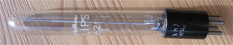
Figure 12. The 4662 current indicator tube introduced in 1935.
The 4662 is the only current indicator tube I know of that was actually commercialized. Most likely it was introduced on the market in the thirties. I have also no idea whether the 4662 originated from Philips Research, or whether it was developed directly by the light division. The 4662 consists of a 6 cm long rod-shaped molybdenum cathode in a 13 mm diameter glass envelope. At the base of the tube we find a small priming anode, and a somewhat larger main anode. The priming anode is always biased to a current of 30µA. This small auxiliary discharge ensures that the main discharge always starts at the base of the tube, rather than at a random point. I own several brand new 4662 tubes which have a completely transparent glass envelope. Since the method of
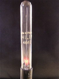 sputter cleaning of the cathode was developed in 1946, the 4662 has an ōun-sputteredö cathode and hence a completely transparent envelope. The grow of the discharge is logarithmic as a function of the current due to the small size of the anode. After intensive use, some unintentional sputtering of the cathode occurs, resulting in a blackening of the glass envelope. According to the Radio museum site the 4662 was used in approximately thirty radio designs in the period 1936 to 1941 [4]. Additionally, it was used as a
grid current indicator in the
Philips grid-dipper GM3121 [5,6].
sputter cleaning of the cathode was developed in 1946, the 4662 has an ōun-sputteredö cathode and hence a completely transparent envelope. The grow of the discharge is logarithmic as a function of the current due to the small size of the anode. After intensive use, some unintentional sputtering of the cathode occurs, resulting in a blackening of the glass envelope. According to the Radio museum site the 4662 was used in approximately thirty radio designs in the period 1936 to 1941 [4]. Additionally, it was used as a
grid current indicator in the
Philips grid-dipper GM3121 [5,6].
Despite the fact that ōmagic eyeö tuning indicators came into fashion, there was still some interest from the ōlight divisionö for the current indicator tubes, probably because they were cheap and directly measured the current without the need for additional circuitry or shunt resistors.
In a Research Report by ōvan Leeuwenö and Botden from 1956 we read that the light division specifically requested an indicator tube with a linear read-out and an extended current range up to currents of 300mA!
The linearity was easily achieved by increasing the length of the short anode in the 4662, to the full length of the cathode. Two types of tubes were manufactured. A small tube with a length of 65mm and diameter of 5.5mm for currents up to 1.3mA, and a tube with a length of one meter and a diameter of 35mm for currents up to 300mA (Fig. 13)! The molybdenum cathode of this monster was kept on mechanical tension by a spring (Fig. 13). At the full indication of 300mA and a maintaining voltage of 120V, it dissipated in excess of 30W. In contrast to the 4662, sputter cleaning of the cathode was considered absolutely necessary to obtain an accurate and linear readout without any discontinuities. The problem with sputtering is that sputter cleaning will also blacken the inside of the glass envelope, thereby obstructing the readout. In the small tube this was prevented by placing the anode in front of the viewing window. The molybdenum atoms readily deposit on the anode so that the anode acts ōas a sinkö for molybdenum atoms. In the large tube a number of nickel anode plates were positioned perpendicular the tube wall. Again, deposition of molybdenum atoms on the nickel in this way prevented the atoms from ever reaching the glass wall. The readout from the large tube was clearly visible at 10m in full sunlight when held against a black background!
Figure 13. Design of a current meter for currents up to 300mA with a length in excess of one meter!
From the work on the current indicator tubes as well as trigger tubes, the concept of the starter in the Z550M was obviously well known. The innovative part of the invention lies in the fact how a rectified AC voltage is used to start and reset the tube 50 (or 100) times a second, whereby a small bias on one of the starter electrodes preferentially ignites one of the digits. The patent on the principle of the Z550M (US3085174), is in the name of two inventors Martinus van Tol and Theo Botden. From the fact that Martinus van Tol is registered as the first inventor we may deduce that the idea originated from him.
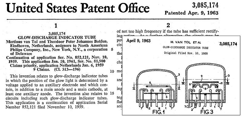
Figure 14. US patent US3085174 on the principle of the Z550M in the name of van Tol and Botden.
Click here to download the patent.
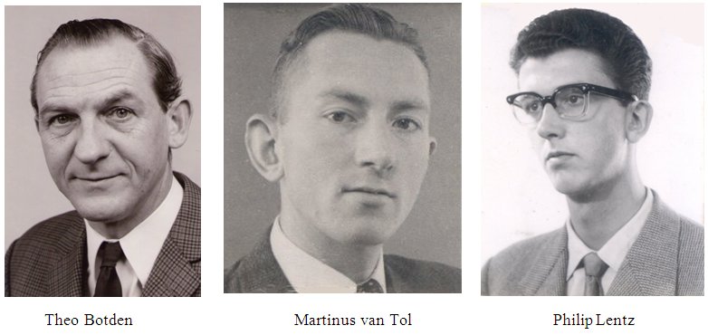
Figure 15. The ōFathersö of the Z550M: Theo Botden, Martinus van Tol and Philip Lentz.
| to top of page | back to homepage |
Philip Lentz was born on the 24th of April 1936 in Rotterdam. After high-school (H.B.S.-B) he studied Mathematics and Physics at the University of Groningen in the north of Holland. On the first of September 1958 Philip joins Philips Research, and he becomes employed in the gas-discharge research group of Theo Botden. After a few months he is assigned to his first real task, the development of what later became known as the Z550M.
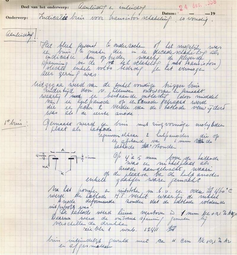
Figure 16. The first page in the Lab Notebook of Philip Lentz coincides with the start of the development work on the Z550M.
Click here or on the picture to download a pdf with a collection of relevant notebook pages.
Lab note-book 6472, page 4, 24th Dec. 1958.
|
It appeared to be desirable to investigate whether it is possible to fabricate an indicator tube that can be used in decade-counters, whereby the output voltage of the counting circuit (with transistors) is only a few volts. And with very little power. Starting point was a trigger tube made by van Leeuwen, in which a first discharge was transferred to a second anode by means of an auxiliary anode , whereby the second anode was at twice the distance from the cathode as the first anode. First sample: A tube with a ring-shaped Molybdenum cathode was made. Two auxiliary anodes were placed on opposite sites of each other at 1 mm from the cathode. At about 4 to 5 mm above the cathode, a nickel anode plate was positioned in which holes were drilled at the position of the auxiliary anodes. After pumping and annealing in an oven at 460C, the cathode was RF heated during which the nickel anode deformed. The cathode was sputtered in 1 mm Ne + 0.1% Ar. Next the strike voltage was measured at different pressures. The tube was finally filled with 11 cm Ne + 0.1% Ar. |
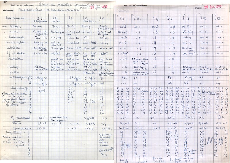
Figure 17.
Example of a page from Philip Lentz lab note-book summarizing a matrix of experiments to optimize the design of te Z550M.
Click here or on the picture to download a pdf with a collection of relevant notebook pages.
Lab note-book 6472, pages 10 and 11, 26th Jan 1959.
The next page relates that in order to prevent the deformation of the anode during RF heating of the cathode, in a second tube the plate shaped anode was replaced by a ring made from nickel wire. In this tube all ten auxiliary anodes were placed and bent parallel to the cathode. The tube was tested with a pulsating DC voltage in order to measure the starter voltages. The test reveal that a 5V starter voltage is enough to select one of the ten positions. However, after several hours of use this voltage increases. This is obviously caused by contamination of the cathode. Several heating/sputtering cycles are used to clean the cathode, with no satisfactory result. Finally, a spectroscopic absorption measurement reveals that the Ne/Ar gas mixture is poisoned with mercury. The following months a series of test samples is made in which many variations in starter electrode shape, annealing temperature, RF heating and sputtering of the cathode are tested. Figure 17 gives a good impression of these experiments.
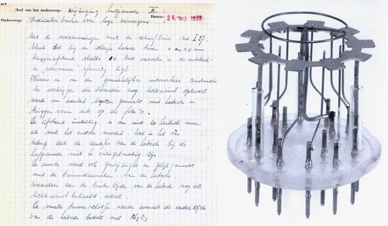
Figure 18.
A description of what appeared to be the best and final electrode configuration. When the tube finally
went into production, the starter electrode was placed in a hole in the cathode.
Click here to download a pdf with a collection of relevant notebook pages.
Lab note-book 6472, page 24, 26th Aug 1559.
From his Note-book entries we see that in the first two months of 1959 Philip is primarily working on the Z550M. Besides starter electrode optimization, he characterizes the behavior of the tube for different frequencies of the pulsating DC bias supply voltage. Gradually however, his activities expand towards other tubes such as a nixie type of numerical indicator tube and current-indicator tubes (Fig. 12). From May to August
1959 there is no reference to the Z550M what so ever. On the 26th of August that year we find the last but one entry related to the Z550M. It appears to concern ōthe finalö electrode configuration (Fig. 18). The page is supplemented by a beautiful black-and-white picture of the tube (note the experimental tube socket with center pins!). The text translated reads:
|
Title: Modification of auxiliary anode; indicator tube for low powers. From observations on ōslider tubeö no. I27 [a tube in which the distance between the anode and the cathode could be varied], we know that for a sharp cathode with a trigger distance between 0 and 4 mm the ignition and ōtransfer voltageö varies only 1V. For this reason, and also to obtain a more manufacturable construction that additionally will increase the brightness somewhat, a number of tubes has been made with a trigger and cathode construction as shown in the photograph. The distance [between the trigger and the cathode] is now less critical. It is however important that the edge of the cathodes is not too rough. The anode was also modified, the diameter of the anode was taken equal to the inner diameter of the cathode, also giving some improvement in brightness. The narrow bridges between the cathodes as well as the bottom of the cathodes is covered with Al2O3. |
Shortly before this entry, the research on the Z550M was more-or-less concluded with the writing of internal Philips Research report No. 3541 entitled: ōA new decade (glow discharge) indicator tube, which can be operated by a low voltage and low energy.ö [7].
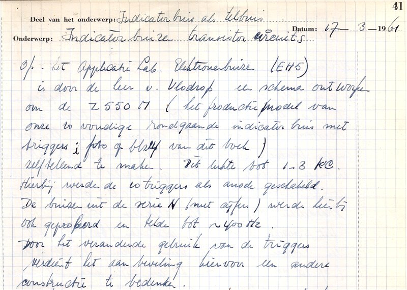
Figure 19.
This note-book entry is dated one and a half year after the last entry related to the Z550M. In the meantime the tube
has been designated the type number Z550M, while the entry also mentions that Pierre van Vlodrop has designed a
ring-counter with the Z550M.
Click here to download a pdf with a collection of relevant notebook pages.
Lab note-book 6472, page 41, 17th March 1961.
| to top of page | back to homepage |
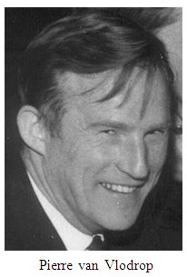
Peter Hubertus Gerardus van Vlodrop, or Pierre as he was called, was born on the 12th of February 1927 in Echt in the province Limburg in the south
of Holland. He studied electrical engineering at the MTS in Heerlen, which is at about fifteen kilometer distance from Echt. During his study he performed an internship with the Dutch state mines. After
he graduated in 1948, Pierre fulfilled his military service in Indonesia, which was at that time a Dutch colony. Near the end of his military duty service, which took more than two years in those days, Pierre received a letter from Philips that invited him to apply for a job. Holland was still rebuilding after the war, and skilled young man and women were in short supply. After Pierre returned to Holland, he joined Philips on the 22nd of January 1951 for an annual salary of 2800 Dutch Guilders. Quite a meager salary if we consider that 2800 Dutch guilders in 1951 is more or less equivalent to 9000 euro today [8]! His contract specifies that he was assigned to the transmission-tube fabrication plant, where his tasks would include: development of new transmission-tubes, the design and improvement of transmission-tube application circuits, and the characterization of transmsission-tubes. Pierre is employed in this group from 1951 until 1956, and the oldest lab note-book dated 1956 that is in the possession of PierreÆs wife, Kitty van Vlodrop, is filled with transmitter circuits.
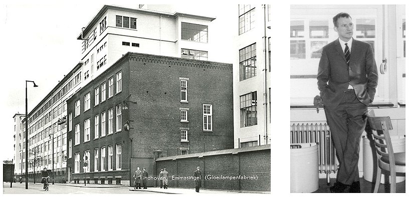
Figure 20. This buiding on the Emmasingel in Eindhoven (left), known as ōThe white Ladyö, housed the largest radio tube production plant in Europe. The development groups were located on the fourth and fifth floors. All Z550M/ZM1050 tubes, regardless of their marking, were made here. The picture is from about the time of the development of the Z550M (see also ōThe Making of the E1Tö).
The picture on the right shows Pierre van Vlodrop standing in his office.
Click here to view an aerial picture of the White Lady.
In 1956 Pierre was transferred to the gas discharge tube development and application group of Jan Scholten, The radio tube application lab at that time comprised the consumer and professional tube application groups, and was headed by Dr. Dammer (see also ōThe Making of the E1Tö). It was located in ōThe White Ladyö on the Emmasingel (Fig. 20). From his note-books we learn that Pierre was primarily working on counting and timing circuits based on trigger tubes like the Z70U, Z71U, Z805U, and the ZC1050. Browsing through his note-books we find an amazing collection of circuits covering almost every conceivable application
ranging from washing machines control circuits via darkroom timers to telephone circuits. It is amazing to read how, despite the fact that the transistor in 1960 was already twelve years old, relatively old technology was still being squeezed to offer price competitive solutions. The darkroom circuit for example consisted of a trigger-tube ringcounter with the tubes arranged in a circular order in such a way that the glow was advanced every second. The exposure time was selected with a dial which moves a CdS photocell in front of the desired trigger tube.
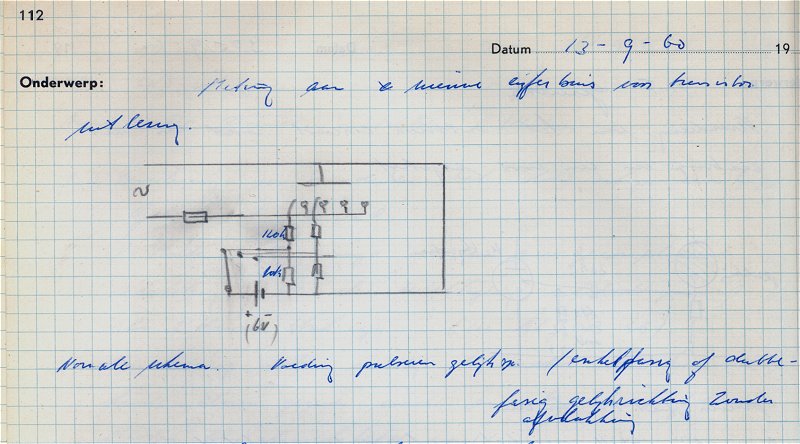
Figure 21. The first entry in Pierre van VlodropÆs notebooks related to the Z550M.
Click here or on the picture to download a pdf of his notebook pages.
Despite the fact that we find only seven pages in VlodropÆs notebooks, which actually deal with the Z550M, his contribution is nevertheless quite substantial since
it was Pierre who developed the ring-counter circuit with the Z550M.
The first entry related to the Z550M is dated the 13th of September 1960 (Fig. 21). The tube is at that time apparently completely new to Pierre, since the figure shows that he first examined the ōstandardö application circuit (Fig. 21). At the bottom of the page we find him measuring something he calls ōthe probe voltageö. The next page makes clear what PierreÆs plans are.

Figure 22. A first attempt to construct a ring-counter circuit with the Z550M.
Click here or on the picture to download a pdf of his notebook pages.
Page 113, which is also dated the 13th of September 1960, shows a first attempt at constructing a ring-counter circuit based on the Z550M (Fig. 22). Translated the text reads:
| The voltage on the probe [starter] charges C1 to approximately 30V. When next the anode voltage is switched off, C1 will be discharged [through the 1M5 resistor], resulting in a negative bias on the trigger [starter] electrode of the next cathode. When the anode voltage rises again, the first discharge will take place between this trigger [starter] and the anode. This pre-ionization will ignite the corresponding cathode. Experiments have been done with C1=1k and 39k without any satisfactory results. Cause? The probe [strater] is badly coupled because of itÆs small dimensions. |
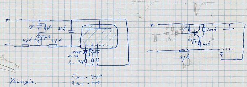
Figure 23. Conception of the Z550M ring-counter circuit. The page is dated 23rd of November 1960.
Click here or on the picture to download a pdf of his notebook pages.
The disappointment with the ring-counter apparently shifts the focus of his attention from the Z550M to other more pressing problems until the 19th of November that year (1960), when there is a meeting with representatives of potential Philips customers for the Z550M (see next section). This meeting apparently revives his interest for the Z550M. What happens next is interesting, because it is exemplary for research and many inventions. While in the ring-counter circuit of Fig. 22 Pierre is still thinking within the boundries of ōthe beaten pathö by trying to use the Z550M in the way it was originally intended, he now steps beyond these boundaries and he rethinks the problem from a completely new and fresh angle. He realizes that if he uses the starters as individual cathodes, he in fact has ten independent neon tubes in one envelope. And very important, since every effort was taken to give these starters as much as possible the same striking voltages, they are as such ideal for the construction of a conventional neon ring-counter. Note, that in this new plan the original cathode is not used at all. I fully realize that this is not a world shocking invention, but it very nicely illustrates the kind of ōaha-erlebnisö which makes the life of us engineers and scientists interesting.
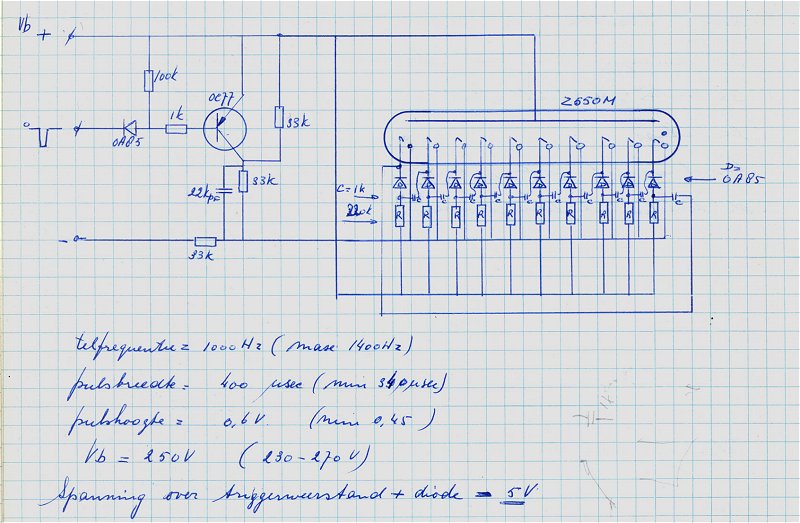
Figure 24 The final ring-counter circuit
The final page in van VlodropÆs note-book dealing with Z550M ringcounters is dated the 16th of January (Fig. 24). It presents the circuit almost in itÆs final form as discussed by Dance [9]. Note that this circuit does not yet contain a provision for a carry to a next counting stage.
| to top of page | back to homepage |
On the 19th of November Pierre van Vlodrop attends a meeting in which the application off the Z550M in Philips products is discussed with several Product Divisions or ōHoofdindustriegroepenö (Main Industry Groups) as they were called in those days. In his note-book we read that representatives from CAB (Centraal Applicatielab Bouwstenen = Central Application-lab Buildingblocks), ICOMA (Industriele COmponenten en MAterialen = Industrial COmponents and Materials), and PIT (Producten voor Industriele Toepassingen = Products for Industrial Applications) were present.
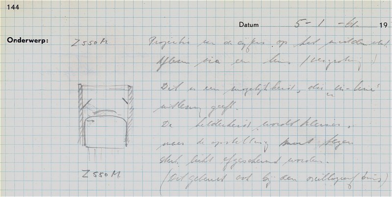
Figure 25. First idea for an in-line read out adapter for the Z550M.
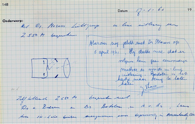
Figure 26. Dr. Morass from the Light Division does not think an in-line readout adapter is feasible.
| Projection of the numbers on a central area. Readout through a lens (magnification). This is a possibility that will give an in-line readout. The intensity will be reduced, so that the tube will have to be shielded agains ambient light, as is done with oscilloscope tubes. |
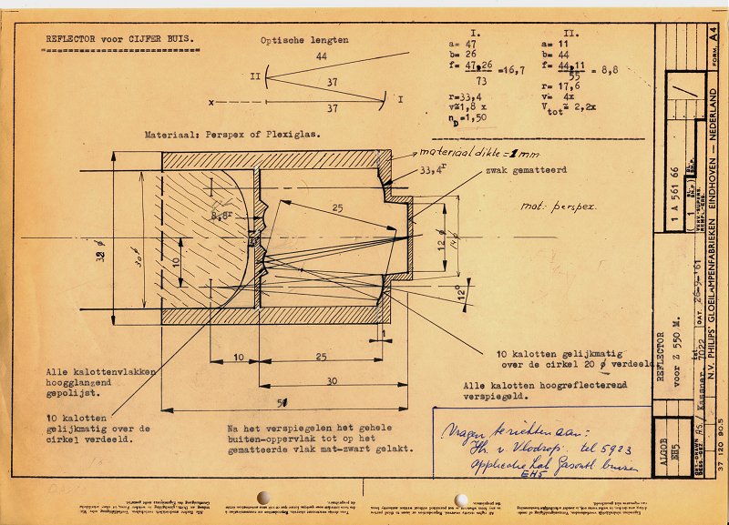
Figure 28. Technical Drawing for an in-line read out adapter for the 550M designed by Dr/ Kassner.
Click here or on the picture to download a pdf with more documents related to the adapter.
Next, Pierre consults Dr. Kassner from the optical research group. He is less pessimistic, and designs the adapter Pierre needs. Figure 28 shows a technical drawing of the design made by Dr. Kassner. The adapter is molded into PMMA (plexi glass), and consist of 10 concave polished and silvered mirrors which project the ten digits on a central concave mirror which in turn projects the digits on a ōfrosted glassö window with a total magnification of a factor of two. The whole adapter was painted black without the exception of the mirrors and the front window. I have the impression that at least one of these in-line read out adaptors was actually made. Unfortunately no pictures or further information has survived, it certainly never became a product.
| to top of page | back to homepage |
The Z550M was not really a commercial succes. Within a few years high voltage transistors were developed
(BSX21, BVcbo=120V) which could drive nixie tubes, making the Z550M obsolete. Z550M tubes with brand names Philips, Valvo, Mullard and Adzam have been reported [10],
 suggesting that the tube was fabricated by several Philips factories across Europe. This is however not the case. The total number of Z550M tubes produced was so small, that they were all produced in the pilot factory in ōDe witte Dameö (Fig. 20) and subsequently labeled according to the country in which they were sold, Valvo for Germany, Mullard for England, Philips for Holland, etc (Fig. 5). In 1966 the European type designation and registration system for active components was set up in Brussels [11]. They to a large extend followed the tube designation system that Philips used, and subsequently the name the Z550M was changed to ZM1050.
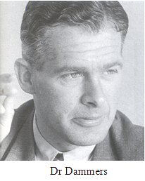
The radio tube application lab was at that time headed by Dr. Dammers, and was often referred to as the æDammers Labö. Dr Dammers who joined Philips in 1945, was the author of several books on radio tubes. His exceptional insight into radio tubes is legendary, and he was the father of many radio and television circuits. The tube application lab designed and tested application circuits for the tubes that Philips manufactured. In this way it bridged the gap between the tube development and production division and the television and radio set-makers, both in and outside Philips. Ir. Hoefgeest remembers how during a presentation in
 Scandinavia of the Application Lab not less than 49 television set makers from Scandinavia alone attended (39 in Spain)! In 1963 the name was changed to CAB (Central Applications Laboratory Building blocks) when the Electron Tube and ICOMA Industriele COmponenten en MAterialen = Industrial COmponents and Materials) divisions were merged to become the ELCOMA (Electronic Components and Materials) division. Contacts with internal customers was intensive from the very beginning. The RGT (Radio, Gramophone and Television) Division, now part of Consumer Electronics, was one of the biggest customers. The arrival of the transistor and the IC to a large extend shifted the focus to the design of television ICs. In 1967 the Application Lab was relocated from the building on the Emma Singel to building BA at the ōBeatrix Siteö also in Eindhoven, where it remained until July 2002, when it was moved to buildings A320 and A410 on the High-Tech Campus in Eindhoven [12].
Pierre kept on working on cold-cathode application for several years. I found one of the most fantastic applications that I have ever seen for cold-cathode trigger tubes in Electronic Applications of 1967. It is a running text display of the type we see everywhere today, but made from trigger tubes instead of LEDs (Fig. 29)! However, unavoidably the transistor gained territory at the expense of cold-cathode (trigger) tubes, and the gas-discharge group was reduced in size accordingly.
At a certain Pierre moved to the RGT (Radio Gramophone and Television) group. At some point of time the RGT group decided to expand its activities towards circuits and electronic applications for motor cars. Pierre joined this group and he even had a special car from Philips that was used to test applications. This activity however heavily upset the Bosch Company in Germany who saw this as its territory and threatened to boycott Philips products if Philips would not stop its car electronics activities. In the end Philips capitulated and Pierre returned to the Application Lab which was by then headed by Ir. Hoefgeest. From then on PierreÆs work is focused on digital circuits and computers. He followed several courses on microprocessors, and was involved in the design and interfacing of LCD displays. After several years of illness, during which he never lost his good humor and optimism, Pierre Vlodrop died on the 14th of December 1984, at the too young age of 57.
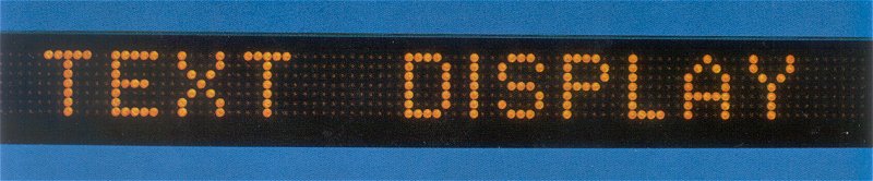
Figure 29. Running Text Display co-authored by Pierre van Vlodrop.
The display uses 700 trigger tubes for the shift register which are also used for the read-out.
Click here or on the picture to read the full article.

Figure 30. Theo Botden is congratulated by Frits Philips, Chairmain of the board of directors of Philips Electronics at that time,
on the occasion of his 25th jubilee. Click here or on the picture to view a clipping from ōde Philips Kourier.ö
After he had undergone a triple bypass surgery, Theo Botden retired the 28th of February 1982 on the age of sixty. After retirement he remained active enjoying his favorite hobbies: tennis, billiards and clubs. The last phase of his life is devoted to the care for his wife who is suffering from Alzheimer disease. On his obituary card he is remembered as a modest man with a strong interest in his family and his fellow man with many friends. A man a few words, who kept his problems to himself, a real Botden.
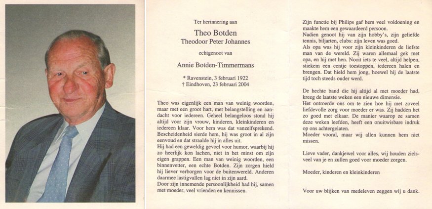
Figure 31. Theo BotdenÆs obituary card.
On the 16th of November 1961, after a relatively short period working for Philips Research, Philip Lentz moved to a commercial position at the electron tube application lab. There he was involved in the commercialization of the Z550M, but also of other indicator and nixie tubes. His responsibilities are later extended towards thyratrons, ignitrons and night-vision tubes. Working for ELCOMA he traveled and lived all over Europe, and is now already for fifteen years enjoying his retirement lifing in France.
I would like to thank the following people for their contributions:
Mr. Philip Lentz, Ms. C.A.M.Th. van Vlodrop-Goedmakers, Tom Botden and familie, Mr. Wil Graat, Mr. Engel Hoefgeest and Corrie Panken and Ad Gast from Philips Research,
http://www.electricstuff.co.uk/oldbooks.html
| to top of page | back to homepage |