The oscilloscope is still one of the most important measurement tools of the electronic engineer. With the advent of the often very reasonably priced USB scopes, such an instrument is now within reach of every body. Twenty five years ago that was quite a different story. A (good) oscilloscope was then a very expensive instrument available only to a happy few. As a result many electronics hobbyist made their own scope. The popular electronics magazines in the sixties and seventies were full of scope designs almost always based on vacuum tubes. This period was closed in 1975 when the Dutch electronics magazine Elektuur (in the rest of the world known as Elektor) published their fully transistorised "Elektorscoop". Despite all this, the purchase of the expensive cathode ray tube and Special high voltage transformer remained too expensive for many people.
In an effort to lower the price for a scope even further, Elektuur published in 1978 the "Videoscope". The Videoscope sampled the analog input signal and stored the samples in a bucket brigade (CCD) memory. Next the data in the CCD was converted into an ordinary (black and white) video signal which could be displayed on an ordinary TV. In order to view the signal in the normal way the TV had to be put on his side, but nobody minded that. All in all it was still a rather complex design comprising a few dozen of ICs and several printed circuit boards.
These days this obviously can be done much simpler. The present generation
of micro controllers is so powerful that such a videoscope concept can
be realized almost completely in software. Recently I obtained a sample
of the 12f675. On examination of the datasheet of this small 8 pins
micro controller from Microchip, it appeared that the small package
contained all the components of a miniature videoscope. In short the
µSCOPE project was born, with as main objective the challenge of
implementing such a relatively complex task in this small micro controller.
The result summarized on this web page is a fully functional (memory)scope
that samples the analogue input signal and subsequently displays it on a
normal TV (Fig. 1).
Unfortunately the µSCOPE works only on 625 line PAL standard TVs, sorry.
It was never the intention to build a
sophisticated measurement instrument. Nevertheless, signals up to a few kHz
are reasonably well displayed by this simple circuit that can be build for
only a few euro. Hopefully this "poor mans" scope may be of good service
to especially the young electronics hobbyist.
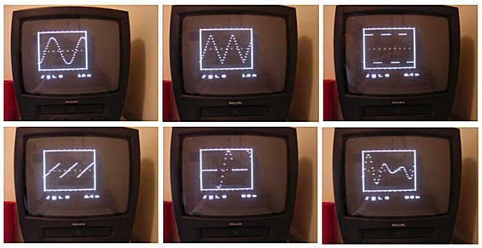
figuur 1. The µSCOPE in action
| to top of page | back to homepage |
The 12f675 is one of the smallest members of the Microchip micro controller family. In the 8 pin package we find a 14-bit processor core, 1k word FLASH program memory, 64 bytes RAM and 128 bytes data EEPROM. Next to the standard peripherals such as two timers, a watchdog timer etc. the 12f675 is also equipped with a 10-bit AD converter with sample and hold, a comparator and a programmable voltage reference. Al these components can be configured under software control and Fig. 2 depicts how this is done for the µSCOPE. Pin 6 is used as the analogue input. Internally this pin is connected via the sample and hold to the AD converter. Since the supply voltage is used as the reference voltage for the AD converter, the measurement range is exactly from 0 to 5V. Pin 6 is also connected to one of the inputs of the comparator to implement the trigger function of the µSCOPE. The trigger level is determined by the programmable voltage reference which is connected to the other input of the comparator. Since it is possible to invert the output of the comparator by software, it is possible to trigger on a positive or negative slope.
The input circuit of the µSCOPE is kept as simple as possible
and can be expanded depending on individual wishes. The input signal is first
DC decoupled by C6. R8 and R9 set the "zero level" at half the supply voltage.
The first line of protection against too high input voltages is provided
by R7, D1 and D2. Both diodes limit the input voltage on pin 6 to a
voltage between 0 and 5V while R7 limits the current.
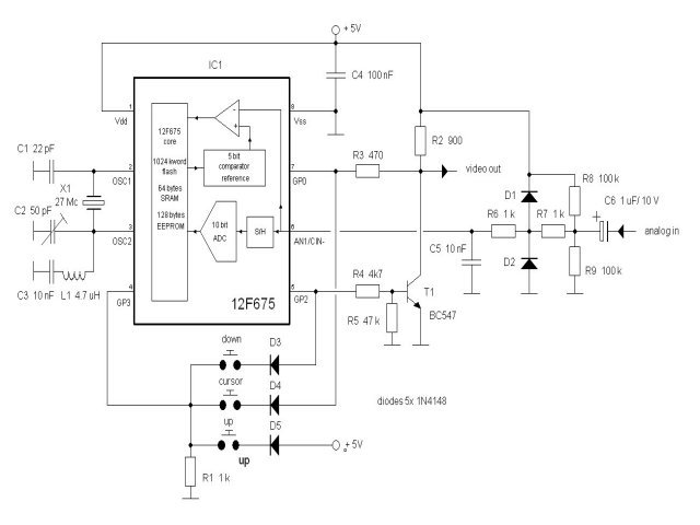
figuur 2. Circuit diagram of the µSCOPE
| to top of page | back to homepage |
I decided not to use interlining. In this kind of applications interlining results in an flickering image while it needlessly complicates the program. The frame frequency is therefore 50 Hz, with every frame consisting of 312 lines of 64 µs (Fig. 3). A line synchronisation pulse of 4 µs indicates the starting of a new line. The frame synchronisation pulse is generated during the first 3 lines of every new frame.
The video and synchronisation signals are combined to a standard composite video signal with a simple circuit consisting of R2-R5 and T1. Resistors R2 and R3 together with the input impedance of the video input of the TV ( (75 ohms to ground) shift a logical 0 on the video output pin GP0 to 0.3V on the video output (black) and a logical 1 to 1.0V (white). A "1" on the sync. output GP2 will cause T1 to pull the video output signal to 0V (ultra-black) resulting in a synchronisation pulse. In principle this circuit could also have been made just by using 3 resistors [1]. This is not possible here. To obtain a high enough speed during the generation of the video signal (e.g. during character generation) data is rotated in the GPIO register. During this operation GP2 is configured as an input to prevent undesired synchronisation pulses. Transistor T1 in prevents an undefined potential at the video output during these moments. GP0 and GP2 have also been used to read the three menu push buttons as can be seen in Fig. 2. This is done during an invisible moment during one of the three frame synchronisation lines.
The maximum clock frequency specified my Microchip is 20 MHz. This was just a
bit too low for a, with respect to aspect ratios, agreeable image. Fortunately
it appeared possible to run the 12f675 at 27 MHz! This is about the limit
indicated by the fact that the oscillator only at 5V supply voltage has
enough gain to start oscillating. Since most 27 MHz crystals are 3e overtone
crystals, a simple filter consisting of C2 and L1 is used to suppress
oscillation at the 9 MHz fundamental.
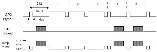
figuur 3. Video timing diagram.
| to top of page | back to homepage |
So simple as the hardware of the µSCOPE is, so complex and challenging was the writing of the software. The real time generation of a complex video signal is in itself already a complex task. In this case additionally an oscilloscope and user interface needed to be implemented! The processor is not only pushed to the limits with respect to speed, also the 1k word program memory is literally used to the last byte. The RAM memory of 64 bytes was even a few bytes to small. Fortunately timer 1 was not used so that its registers could be used as 2 additional bytes of memory. The scarceness of memory and speed stimulated the seeking for inventive solutions. Of course I could have used a larger or faster processor, but that would have spoilt part of the charm of the project.
At a clock frequency of 27 MHz every line of 64 µs takes exactly 432 machine cycles. One cycle longer or shorter results in a distortions of the TV image. This means that if a piece of program that is executed during the writing of a line contains branches, every branch needs to be exactly equal in length. Since in general this is obviously not the case, we need to add NOP instructions to the shorter branches until they have the same length as the longest one. How this is done is illustrated by a piece of virtual program in Fig. 4. In this example we find a routine which decrements a double byte counter at every call. When the counter reaches zero, it is initialised again to some preset value. In the flow diagram of Fig. 4 the three branches of the routine have been identified as: A, B and C. The assembler code above the dashed line represents the longest branch C. Next the number of machine cycles is calculated for every branch. It appears that branch C uses 9 cycles. The piece of assembler code underneath the dashed line is needed to increase the length of branches A and B with NOPs so that they also get a length of 9 cycles. If memory is scarce (as for the µSCOPE) then in a final optimisation all double NOP instructions can be replaced by a single GOTO (the execution of GOTO takes two cycles). Undoubtedly there are compilers which are very clever in this kind of program optimisation, but in this case the whole program was written by hand. The assembler code of the program can be downloaded at the bottom of this page. The abundant amount of comments in the code should make it possible for everybody to follow the program.
The largest part of the program is taken up by the synchronous routine which takes care of the generation of the video image (sync_blck). In order to split this routine into manageable chucks, the total video image was subdivided into a number of line types. Every line type is generated by a separate subroutine recognizable in the code by the label "line_xxx". The routine line_sync for example generates the frame synchronisation pulse. The routine "line_blank" generates a black line while routine "line_view" displays the actual scope image etc. etc.. A "routine dispatcher" calls every line routine at the right moment for a certain number of times, until the total frame consisting of 312 lines is composed.
In order to deal with a number of tasks such as the user interface in an
asynchronous way, the synchronous routine is exited
during a part of some lines (line_async) in the black upper part of the
screen. Before the synchronous routine is left however, timer 0 is set
so that it will generate an interrupt just before the next data sample is due.
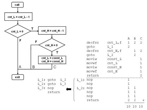
figuur 4. Example illustrating how a program can be made to have a constant
execution time by adding NOP instructions.
| to top of page | back to homepage |
Fifty of the 64 RAM bytes are reserved for the storage of the 50 data samples. Although the AD converter has a 10 bits resolution only the 7 most significant bits have been used. These 7 bits represent 128 voltage levels between 0 and 5 V, corresponding to a part on the TV screen with a height of 128 lines. The routine "get_AD" takes care of the actual data acquisition. This routine is called 4 times every line so that the minimal time between two samples is 64 µs/4 = 16 µs. The first task of the routine is to take care of the trigger function. Has a trigger already occurred and is the sample memory not yet completely filled, then a new sample is stored. In case a trigger did not yet occur, the routine checks if perhaps in this call a valid trigger occurred. In case the time base is adjusted to a lower sample rate then, depending on the time base setting, only 1 in 2, 1 in 4, 1 in 8 etc. samples will be stored. Advantage of this method is that the trigger function will run at maximum speed independent of time base setting so that time base jitter will be minimized.
The stored data samples are used by the synchronous part of the program
to construct the image on the TV screen. As already mentioned, every one of the
128 possible measurement values corresponds to one of the 128 lines in the
scope frame on the screen. The scope signal is constructed by comparing for
every pixel on the screen the corresponding sample value with the
momentary line number. The pixel is switched on if they are equal and remains
dark if not. A straight forward programming of this function would at least
cost 5 instructions. Too much for a nice small pixel. A trick is therefore used
whereby a cyclic incrementation of the measurement data is used. The principle
of this cyclic incrementation is explained in Fig. 5.
In the simplified example of Fig. 5 9 data samples have been taken from
saw tooth shape signal. There are only 6 possible sample values (0-5).
For every new line on the screen all the samples are incremented.
A pixel is switched on of during this incrementation a carry occurs
(transition from 5 to 0). If not the pixel remains dark. Observe that after
6 lines the samples have been restored to their original value.
Fig. 5 also gives the assembler code for this procedure. By shifting the
carry from the Status register directly into the video output bit (bit 0
of GPIO) the need for time consuming conditional branching is elliminated.
We see that for every bit only two instruction (cycles) are needed!
Looking at the "line_view" routine in the assembler code it can be seen
this was actually too fast and that for every pixel a NOP needed to be added.
The only disadvantage of this method is that it consumes relatively a lot
of program memory.
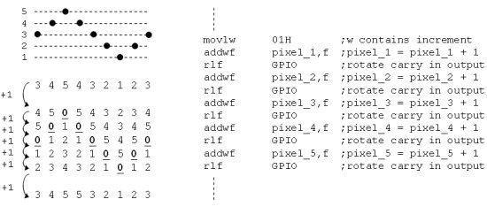
figuur 5. Principle of how the image is formed by cyclic incrementation of the
measurement data.
| to top of page | back to homepage |
A relatively large part of the program deals with the user interface. Control of the µSCOPE is done with the three pushbuttons and a few simple menus underneath the scope image. The generation of the characters in the menu was quite a challenge in itself. The time between two characters is so short that in this time only a few instructions can be executed. All text therefore has to be ready bit-mapped in memory before we start writing the text lines. Since all the RAM memory was already used for sample storage and the working registers the EEPROM memory was used for this purpose. Although writing in the EEPROM is slow (several ms), reading from it (indirectly) fortunately can be done at full speed. Writing of the bit-mapped characters into the EEPROM is done by the asynchronous part of the program which, as already mentioned, takes care of the user interface. Using a character look-up table the characters are scattered over the EEPROM memory in such a way that the synchronous routine ("line_txt") can read them sequentially at high speed.
Control of the µSCOPE is very simple. By pushing the cursor button the cursor can be shifted to one of the five menus. Next the selected setting can be changed by pushing the up or down keys. In the left menu a choice canbe made between normal operation, freezing of the image, or a hybrid form whereby the input signal is only sampled for a fraction of a second after which the image is frozen. The last function gives a less "nervous" image at higher frequencies. In the second menu a choice can be made for the trigger polarity (pos,neg) it is also possible make the time base free running (-). With the cursor underneath the third menu, the trigger level can be adjusted by pushing the up or down keys. The trigger level is made visible by a small marker along the left y-axis of the scope image. The fact that only a limited number of trigger levels can be selected is a limitation of the internal voltage reference. By pushing the up (or down) key with the cursor underneath the S all the setting will be stored in EEPROM. If the scope is power-up the next time these setting will be automatically reloaded. In the last menu the time base can be adjusted. The time displayed in the menu is the total time for all 50 samples. Since only 2 characters where available some rounding of the numbers was needed. The exact time base values are: 0.8, 1.6, 3.2, 6.4, 12.8, 25.6, 51.2 and 102.4 ms.
| to top of page | back to homepage |
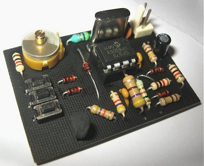
The circuit of the µSCOPE is so simple that it can easily be build on a piece of test PCB (Fig. 6). Be sure that the contact of the variable capacitor that is connected to the metal "screw" is connected to ground. If you connect it the other way around the oscillator will halt when you adjust the capacitor with a metal screwdriver. For the programming of the 12f675 I use a "Tait style" programmer [2] that is controlled by my PC (an old 286 laptop !!) via the printer port. I used the PP06 program [3] running under DOS (I thoroughly detest anything working under WINDOWS). If you would like to use something more advanced then the WISP programmer by Wouter van Ooijen is a good alternative [4,5].
The whole circuit consumes less than 10 mA, so it is very well possible to operate the µSCOPE from a 4.5 V battery. After the circuit has been checked for any mistakes the video output is connected to the SCART (or AV) input of the TV. After the battery is connected C2 is tuned until a stable image appears. It might be necessary to briefly disconnect the battery to make the oscillator start after C2 has been adjusted. The µSCOPE is now ready for use. A simple amplifier may be added at the input if you want to increase the sensitivity. Since we are not dealing with a sophisticated instrument a standard Op-Amp circuit will suffice. A nice extra is the possibility to record the µSCOPE image on a VCR!
If after a while you get a little bored with the µSCOPE you might want
to try to make your own video-generating program. To lower the threshold
to start experimenting in this direction you can use the program EXAMPLE.PIC.
This stripped down program, just displays a rectangle, a dashed line and a
dotted line. It is so simple that it is very easy to follow what is going on,
and it allows you to make simple additions and alterations. If you live
in a country with a different video standard, this program may be your
starting point to adjust it a different standard. With some creativity
undoubtedly a lot of other fascinating video generating circuits may be
created. Hopefully working on it will give you as much pleasure as I have had
with the µSCOPE.
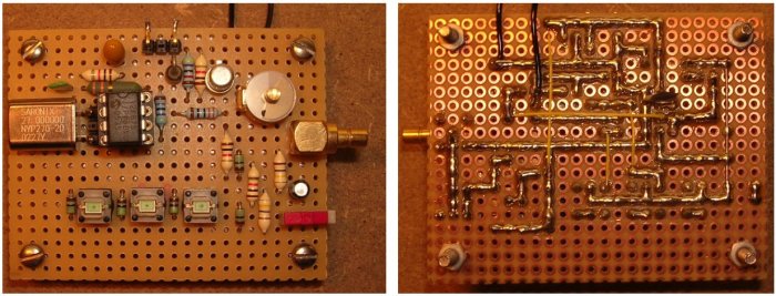
figuur 6. The µSCOPE on a piece of breadboard
| to top of page | back to homepage |
download here a compresed folder with schematic, source and hex files
Piotr Gluszenia Slawinski developed a version of the µScope that runs on a 28.496 MHz resonator. The adapted software and a description can be downloaded here.
| to top of page | back to homepage |
µSCOPE at work. Note how the cursor at the bottom is used to control the functions.
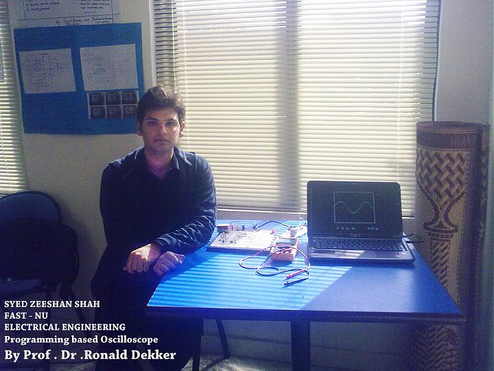
Syed Zeeshan Shah made a university project out of the µSCOPE. Well done!!
Dmitrij Kazakov’s verion of the µSCOPE
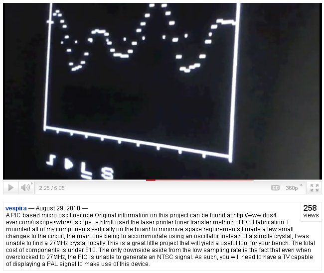
Vespira’s version of the µSCOPE on YouTube