|
Contents:
|

|
|
Contents:
|
|
Philips Research in Eindhoven (The Netherlands) is a place full of remarkable people and old traditions. One of these traditions is that whenever a jubilee is celebrated because somebody is 25 (or 40!) years with the company, or when somebody retires, there is a “home-made” present next to the official reception. Despite the fact that a lot of things have changed over the years - some say “have become more professional” - and that everybody is pestered with projected bounded budgets, this tradition is still kept alive by clusters of old diehards. My colleague (and friend) Eugene is at the centre of one of these clusters, and it is he who usually takes the initiative in organizing something when somebody in our group of acquaintances is due for a jubilee or retirement.
Last April it was Eugene’s turn to celebrate his 25th anniversary with Philips Research, so we made sure that we also had a “home-made” present for him. Since we work in the field of Silicon Wafer processing, invariably silicon wafers, in one form or the other, constitute part of the present. One of the more common presents is a Silicon Wafer provided with some text, a drawing or a photograph etched in a thin aluminum layer sputter-coated on a silicon wafer, preferably against the background of a layer of deep blue silicon-nitride. Since ages it has been very popular to combine such a wafer with a clock. In this case it turned out to be a very unusual clock.
Last year, the old RBS (Rutherford Back Scattering) measurement setup was dismantled. The control panels of this rather immense machine contained a large number of analog meters which I personally removed. It had been a longstanding idea to build a clock in which the hours, minutes and seconds are indicated by separate analog meters. I know that Eugene has many good recollections of the days when the RBS setup (and all the other beautiful equipment in that building) was in full operation, so it seemed the perfect opportunity to use some of the meters from the RBS and built him a digital-analog-meter-on-a-silicon-wafer-clock. Just the thing everybody wants to have in his (or hers) living room!? There is also a link to the present: a series of color LEDs behind the clock provide a continuously changing “ambient lighting” display.
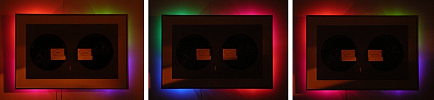
Figure 1. “Ambilight” has almost become a standard feature on all my clocks.
| to top of page | back to homepage |
The circuit diagram of the meter-clock is very straightforward since all functions are controlled by a 16F628 PIC micro-controller (Fig. 2). The analog meters are driven by a Pulse Width Modulated (PWM) signal from outputs of the controller. The PWM signal is generated under software control. It is a square-wave signal with a variable duty-cycle between 0 and 100%. The repetition frequency of the PWM signal is high enough so as not so cause any vibration of the needle. The meters I used were of the type that rest in the middle position when no signal is applied. For this type of meters the circuit in dashed box A is used. In this case two small potentiometers are used to set the meter to half-scale (P2) and full scale (Px). By keeping S1 pressed during power-up, a special test procedure is initiated which aides the adjustment of these potentiometers. For normal meters with the needle in the left position with no signal applied, the circuit in dashed box B can be used. Here only the full scale needs to be adjusted. The values of Rx and Px depend on the sensitivity of the meters used. If you are not sure it is a good idea to start with a rather high value of something like 750K and then decrease this value if the full scale cannot be reached.
Figure 2. The circuit diagram of the “meter-clock”.
Click here or on the picture to download a pdf version of the circuit diagram.
Also the ambilight feature is driven by PWM signals generated by the controller. I used small three color SMD LEDs which were connected in parallel. By permutation of the three connections to the LEDs (RGB, RBG, BGR, BRG, GRB, GBR) each of the LEDs has its own random color (Fig. 1). Transistors T1, T2, and T3 are used to buffer the outputs of the PIC while the common anodes are fed connected to the unregulated power supply so as not to unnecessarily load the LM317 regulator. The software that controls the random changing of the color of the LEDs is only one routine that was originally developed for “Jan Verhoeven’s farewell present”. Since then I have used it in a number of clocks (”Geert’s clock”, the “Tube-In-Tube clock”).
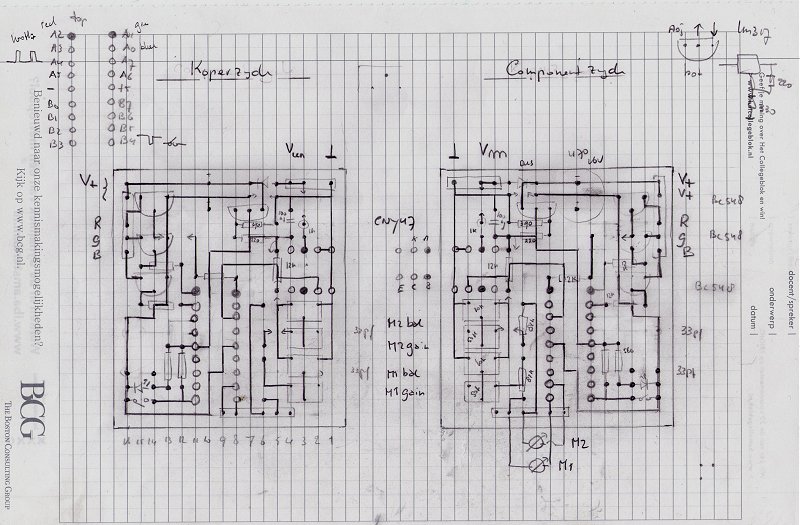
Figure 3. The design for the “PCB” of the meter-clock.
For the power supply an old Nokia charger of the type ACP-7E was used. This is a very common type which is rated at 3.7V at 350mA. It is nice and small and is only provided with a bridge rectifier and not a smoothing capacitor. This is useful since I use the 50Hz mains frequency (100Hz after double-sided rectification) to keep the time. This actually is a point of fierce debate. I frequently get emails from people who say that in the countries they live in, the mains frequency is an absolutely unreliable time standard. Without doubt this holds for many countries, however, I also firmly believe that in many parts of the world the long term stability of the mains-frequency is very well maintained. It is my personal experience that clocks which derive their time standard from the mains frequency are extremely accurate, although they can show deviations in the order of say half a minute depending on supply and demand of power. That does not mean that the mains signal does not need any conditioning, the switching of inductive loads can cause quite large spikes on the mains which can add up to substantial errors in timekeeping. Opto-coupler IC3 is the first line of defence against these spikes. The opto-coupler first of all prevents these, potentially high-voltage spikes from reaching the processor, and secondly filters out the shortest pulses since it is a relatively slow device. The software furthermore provides additional filtering.
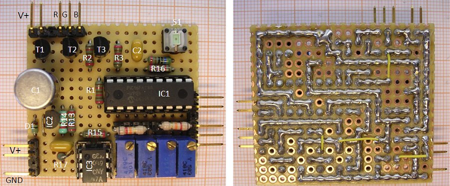
Figure 4. The final circuit of the meter-clock.
The software also generates a PWM signal for a meter for the seconds. This output is available on pin RB1 and can be connected to a meter in the same way as the minutes and the hours. In the version of Fig. 4 only a meters for the minutes and hours are used.
| to top of page | back to homepage |
The program for the Meter-Clock is relatively straight forward, and consists mainly of blocks which have already been used in e.g. the Tube-In-Tube Clock. For me one of the interesting things was to puzzle out a routine which would efficiently generate the PWM signals for the meters. From time to time, I get mails from people who have difficulty in writing an assembler program for their clock themselves. To help those people along, I will try to explain the program in reasonable detail. In this section I will discuss the general architecture of the program, and in the next section I will go through the program in greater detail filling in all the routines. In the final section on the software I will discuss the for me most interesting part: the PWM routine. The complete assembler input file as well as the hex code and the assembler itself can be downloaded in the download section at the end of this page, or by clicking here.
The program itself consists of two main parts (Fig. 5): the main-program and the interrupt service routine. Despite what the name suggests, there is not that much going on in the main program. The main program takes care of the setting of the time when the key is pressed, and also the calibration routine is implemented in the main program. In normal use however, the main program will spend most of its time just waiting until the key is pressed. The interesting stuff is going on in the interrupt service routine(s).
Figure 5. The flowchart of the software for the meter-clock.
The interrupt service routine is called on an overflow of one of Timer0. In fact the interrupt service routine itself calls a cascade of separate routines that: deal with the random changing of the colors of the LEDs, the filtering of the 100 Hz input signal and the time keeping. These routines communicate with each other and the main program through a set of flags and variables. In Fig. 5 the black lines indicate the flow of the program, while the red lines indicate the flow of data through flags and variables.
The first thing that is done when the interrupt service routine is called is that a number of important processor registers are saved by the “pop” routine. Next routine “rnd_col” is called. This rather complicated routine is described extensively on the page on “Jan Verhoeven’s farewell present”. The routine works fully autonomous and uses PWM to slowly change the colors of the LED’s stepping through a table (“c_table in file GROUP2.INC”) of randomly picked color points.
Routines: “flipflop”, “filter”, “second” and “time” deal with timekeeping. Routine “flipflop” samples IO pin RA4 and when a 0 to 1 transition is found, sets the SYNK flag. Routine “filter” waits until the SYNK flag becomes set. When set, routine “filter” first resets the SYNK flag and then for the next 44 calls (8.8 ms) ignores the SYNK flag. In this way all spurious transitions of the input signal are ignored during this period. On the next SYNK, the routine assumes that a valid 100Hz period has elapsed and responds by setting the NEW100 flag. Routine “second” monitors the NEW100 flag and when the routine finds it set, responds by first resetting it. Next when it has counted down 100 of these events, it sets the NEWSEC flag to signal that a new second has elapsed. The routine “time” finally polls the NEWSEC flag and when it finds it set – after first resetting the NEWSEC flag – increments the time which is stores in variables SEC, MIN, and HRS. It does so only when the GOTIME is set. The GOTIME flag is controlled by the main program. When the main program is in interaction with the user to set the time, the GOTIME flag is reset so that the time is not accidentally incremented. At the end of the time set procedure, the main program sets the GOTIME flag, and the clock starts ticking. It is important to realize that these routines are all called every 200 us and that most of the time they do nothing.
The last two routine to be described are the “pwm” routine and the “inkey” routine. The “pwm” routine uses the values stored in “SEC”, “MIN”,and “HRS” and generates a PWM signal accordingly. The precise working of this routine will be discussed in one of the next sections. Finally, routine “inkey” monitors IO pin RB4 which is connected to the press-button. The routine detects when the key is pressed and debounces the signal. When it has determined that a valid “key-pressing event” has occurred, it sets the NEWKEY flag. The part of the main program which is responding to this event also has to reset this flag.
| to top of page | back to homepage |
The first step in the program is the setting of the configuration word in line 6 (click here to download a pdf version of the assembler input file). As the name suggests, this word configures some of the internal hardware features of the processor. The most important features set here are the selection of the internal 4 MHz oscillator and the disabling of all kinds of features which can protect the program memory from being copied.
Next some constants and variables are defined [line 44-87]. At this stage these are just symbolic codes which the assembler substitutes during the final assembly of the program. “NCYCLE_REL” and “NBURST_MAX” are used by the random color routine. “FILTREL” holds the duration of time the mains filter routine blacks-out after detection of a “SYNK,” in this case 02Chex = 44dec = 44*0.2ms = 8.8ms. In “MAXHRS” it is possible to set the number of hours one wants to display on the meter 12 (0CH) of 24 (18H) [line 50]. “Mains” finally sets the mains frequency 50Hz (32H) of 60Hz (3CH) [line 51]. In the section where the byte wide variables are defined [lines 65-87], two bytes are reserved for the flags, or the bits [lines 65,66]. In “The Bits” section [lines 55-61] the position of the flag within these bytes is assigned to a flag name.
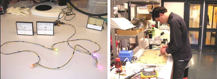
Figure 6. Was it not for the invention of double-sided adhesive tape, these kind of presents would be simply impossible!
After a reset or power-up the processor starts executing instructions from address 0000. The code in lines 90 and 91 take care that after a reset the processor immediately jumps to the initialization routine “init”. When an interrupt occurs, for instance by a timer overflow as in this program, the processor continues executing code from location 0004. The two lines 93 and 94 make the processor jump to the interrupt service routine “tmrint.”
Finally, the main program starts in line 97 with the initialization of the relevant registers in the processor, e.g. to define which pin is input or output, to select and start Timer0 as the interrupt source etc. [lines 97-118]. Immediately after execution of this piece of code, Timer0 will start interrupting the processor every 200 us. Next, the variables and flags used by the program are given their initial values [lines 121-152]. The body of the main program starts in line 156. First the program checks if the key is pressed. If so, it was pressed at power-up, meaning that the program has to start the meter calibration procedure by continuing with label “main_2” [line 162]. If the key was not pressed at power-up, the program continues with the part in which the time is set at label “main_6” [line 187].
The calibration routine [lines 162-184] is actually very simple. What happens is that the processor, by programming the bytes which set the time (“HRS”,”MIN”,”SEC”), alternatingly directs the needle of the meters to the left, middle and outer right positions every time the button is pressed. In lines 166-168 we see how the processor waits with the next action until “NEWKEY” becomes true, then resets this flag and continues. This piece of program loops indefinitely, and the user has to disconnect the power to return to the normal clock mode. In the remainder of the main program the hours and minutes are set.
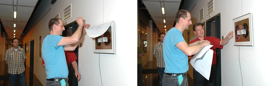
Figure 7. The moment when your wife’s worst nightmare becomes true, you get a homemade clock from your colleagues!
The main interrupt service routine which is called every 200 us can be found in lines 250-264. The first thing this routine does calling routine “push” to save the working register W, the STATUS byte and PCLATH. Next the interrupt flag is reset to enable new interrupts and Timer0 is reloaded to ensure that again after 200 us an interrupt will occur. Next one by one the routines are called which have been discussed in the previous section. The other routines are all pretty straightforward. The most complex routine is “rnd-col” which uses a table with random color point which is located at address 0300H. The table can be found in include file “GROUP2.INC” which is included in the main program in line 536. As mentioned before, the “rnd_col” routine is discussed extensively on the page on “Jan Verhoeven’s farewell present”. The pulse width modulation routine is discussed in the next section.
| to top of page | back to homepage |
The routine that generates the Pulse Width Modulated (PWM) signals for the analog meters is interesting because of its simplicity [lines 362-389]. The basic concept of the routine is explained in the flow diagram in Fig. 8. In this example the generation of the PWM signal for the hours meter is shown, and for the sake of the flow simulation in the right part of Fig. 8 it is assumed that there are only 5 hours in a day.
The heart of the routine is counter hrs which is decremented every time the routine is called. When the counter reaches zero, it is reloaded with the number of hours in a day: 5 in this example! At the same time the output is made ‘0’. Next, the counter is compared with the variable which holds the hours part of the time. If they match, the output is made ‘1’. The simulation on the right part of Fig. 8 illustrates the working of the routine.
Figure 8. Flow diagram of the pwm routine (left) and an example “for a 5 hour day” on the right.
Note that when hrs equals the reload value, the output is high almost all the time except for the few instructions between the point where it is reset and set again. In practice this can be neglected. The code for each PWM generator takes only 9 instructions, and in the pwm routine is repeated three times for the seconds, minutes and hours.
| to top of page | back to homepage |
When the clock is powered up with the switch pressed, it enters the “meter calibration” mode. The software moves the needles of the meters to the extreme left, half scale and the extreme right every time the button is pressed. This mode can only be exit by switching the clock off.
When the clock is switched on without pressing the switch, the normal clock mode is entered. When next the switch is pressed once, the software starts incrementing the hours at a pace of one per second. When the correct number of hours is reached, the user presses the switch. This stops the hours from incrementing, and starts the incrementing of the minutes. When again the switch is pressed at the correct time, the clock waits for a final press on the button to start the clock.
| to top of page | back to homepage |
The assembler input file as well as the assembled hex file can be downloaded by clicking here. I have included the DOS assembler that I always use. It is a bit old fashioned but it works perfectly and does not take much disk space. To assemble the code, just unpack all the files into a directory, open a command prompt in this directory and issue the command: “MPASM EUG.PIC”
The files included are:
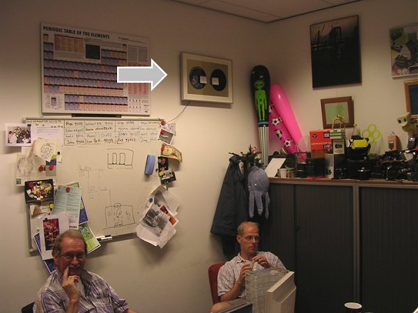
Figure 9. The meter-clock didn’t quite make it into the living room, but also in this modest corner,
it is highly appreciated by over enthusiastic colleagues!
Hello Ronald,
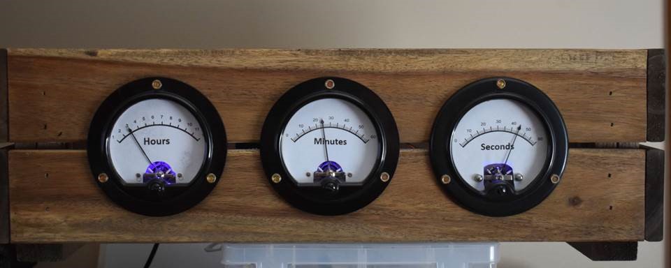
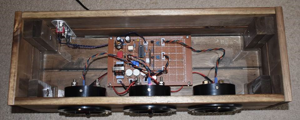
I hope you and your family are safe during these Covid19 times. In spite of already being retired I found myself with extra time, since I could not do many of the visits etc. I am used to doing. So time to dig in various boxes to come up with something to build. I came across a box with old analog meters, and I remembered the clock project on your site. Of course just duplicating someone else’s work is too easy, as well I found that due to differences in the compiler you seem to have used I had to dig in the software to make some adjustments. So why not also look at the hardware. I made some changes in the way the timing pulse is extracted, and this resulted in a beautiful narrow square pulse. I added the AC filter simply because I had a bunch of them, and I like the smell of solder. Detection of the timing pulse is through the External Interrupt function of the PIC, which allowed me to simplify the software. I brought the light fade function in, and since I wanted to try out the three options, I decided to add a selector switch that allows me to select the three options on the fly. I also added the ASM file in case you are interested. The meters I used were 1 – 0 – 1 mA type, so I needed to use the centering option. I slightly modified that from your design which gave me a slightly better response from the pots.
The box is always a challenge in any build, and in this case my solution came from Ikea of all places. The box is actually supposed to be a planter box, but was just perfect for my purpose.
So thanks again for the inspiration and sharing of your wonderful projects!
Bill van Dijk
Download Bill’s design files here
Have a look at Charles’ “analog” frequency counter!
| to top of page | back to homepage |