|
The making of the E1T or The making of the Z550M/ZM1050 or The importance of the emergency landing of a German seaplane in 1917 For the early development of Philips Research. |

|
The EF50 RF penthode constitutes a landmark in the history of the radio tube. Before the EF50, all radio tubes were fabricated using technology which was directly derived from the technology for making light bulbs. The EF50 in contrast had, like all ďmodernĒ radio tubes, a base made from pressed glass. This enabled the designers at Philips to combine superior performance with a low-cost high volume production technology in a single tube. Several accounts of the history of the EF50 have been given, both in literature as well as on the Web [1]. On this page I have tried to gather all this information, and to go as much as possible directly to the sources. I have tried to sketch the context of the development of this tube and included an account of the history of Radar and the history companies like Pye, Mullard and Philips in as far as it is relevant to the story of the EF50. Using unique Philips sources, special attention will be given to the novel fabrication technologies that were used for the EF50. Finally, and for me personally most interestingly, I have tried as much as possible to reveal the people behind the technology.
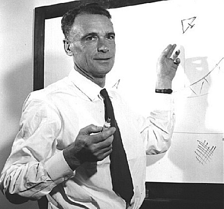
Figure 1.1 Edward George ďTaffyĒ Bowen.
| to top of page | back to homepage |
Edward George ďTaffyĒ Bowen was born the 14th January 1911 in Cockett near Swansea, Wales [2]. Being highly intelligent, he was able to get a good education by winning scholarships. From a very early age he developed a strong interest in radio (and cricket). He studied physics at Swansea University College and graduated with First-Class Honors degree in 1930. He completed his doctorate under Professor E.V. Appleton at Kings College London. [3] In 1926 Appleton had proven the existence of the first ionospheric layer (now called the E-layer) by the reflection of radio waves. In 1947 Appleton was to receive the Nobel prize for his contributions to exploring the ionosphere.
As part of his research, Bowen spent a large part of 1933 and 1934 at the Radio Research Station at Slough. In the early months of 1935 an advertisement for a job position at the Radio Research Station was issued and Bowen decided to apply. After a very relaxed interview with Watson-Watt, the superintendant of the institute whom he already knew from his PhD work, he was given the position. He joined the staff of the Radio Research Station towards the end of April 1935 as a Junior Scientific Officer. By then he was still completely unaware of the fact that the Radio Research Station harbored a great secret. But that was soon to change: on his very first day he was introduced to the provisions of the Official Secrecy Act, which stated the penalty for the slightest deviation from the most meticulous standards of security: ďto be hanged by the neck until life was extinct!Ē After he had signed the contract, a highly impressed Bowen was told of the secrets of Radio Direction Finding (RDF), better known as Radar.
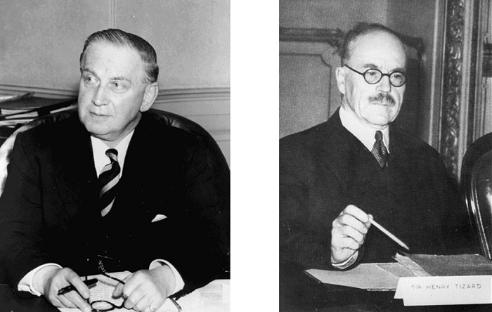
Figure 2.1 left: Sir Edward Victor Appleton (1892-1965), right: Sir Henry Tizard (1885-1959).
Radar had been "in the works" in Germany as early as 1933. Not long after that also England, France, Holland, Italy, Russia, and the United States started research projects along the same lines. Only England however, really pushed Radar and its practical use, and integrated it into their fighter command network. By the time the Nazis were ready to start the blitz of England in July 1940, England had 29 Radar stations making an invisible curtain along its southern and eastern coasts. According to Bowen, this was largely due to the vision of one man, Sir Henry Tizard.
Tizard was a chemist by training and he had spend a year working in Nernstís laboratory in Berlin in 1908. As such he knew the German people and he had a first-hand experience of that country preparing to go to war. During World War I Tizard served in the Royal Flying Corps and in 1917 he was in charge of the scientific work of the Aeroplane and Armaments Experimental Station. Between the wars Tizard held a variety of governmental posts, perhaps the most important of which was Secretary of the Department of Scientific and Industrial Research. As such Tizard was very much aware of the length of time which must elapse between initiating something at a research level and its practical application.
In 1934 Tizard was the rector of Imperial College. Towards the end of 1934 he began to think about the problems of air defense and what could be done about it. He realized that in a few yearsí time, Britain would be subjected to a devastating air attack and, as things stood, the country was defenseless against it. Most likely on initiative of Tizard himself a committee was formed to consider this problem. The committee consisted of P.M.S. Blackett [5], A.V. Hill [6] and H.E. Wimperis, with Tizard as Chairman. It became known as the ďTizard Committee.Ē
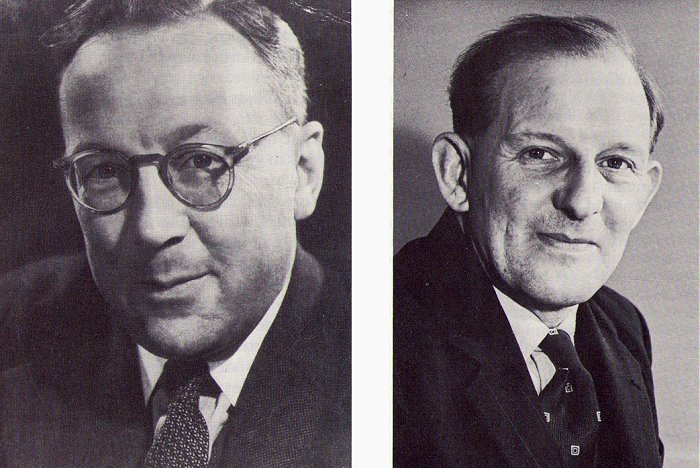
Figure 2.2 left: Sir Robert Watson-Watt (1912-1973), right: Arnold F. Wilkins.
There were at that time numerous rumors that Germany had developed a ďDeath ray.Ē Engines would stop and animals and people would drop death when subjected to such a death ray. To assess the truth of these rumors the Tizard committee decided to consult Watson-Watt. Watson-Watt was at that time the Superintendent of the National Physical Laboratory (NPL). As a physicist Watson-Watt had worked on the detection of dangerous thunderstorms. To do this he had designed an elementary radio direction finder which on a cathode-ray tube gave the direction of thunderstorm activity. Watson-Watt passed the ďdeath rayĒ question on to Arnold Wilkins, and asked him to calculate how much energy would be required to damage an aircraft or adversely affect the crew. The answer came out at an impossibly high figure. However, in the course of making his calculations, Wilkins realized that if radio waves were sent in the direction of an approaching aircraft, while no damage would be done, there was a possibility of something quite different, namely detection of radio waves reflected back from that aircraft.
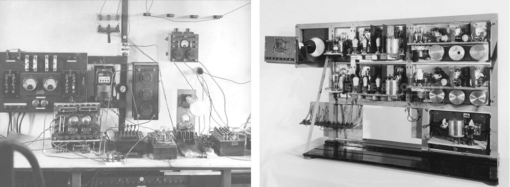
Figure 2.3 left: Watson-Wattís apparatus for studying waveforms of ionospherics (ca. 1924), right: The original equipment used by Watson-Watt and Wilkens in 1935 to demonstrate the principle of Radar.
This proposal was put forward in the famous memorandum ďDetection and Location of Aircraft by Radio MethodsĒ which Watson-Watt submitted to the Air Ministry on the 12th of February 1935 [7]. By a happy coincidence, the Air Member for Research and Development at that time was the legendary Air Vice-Marshal Sir Hugh Dowding, the man who was destined to play a vital role as Commander-in-Chief during the Battle of Britain. In his gruff way, his first reaction to Watson-Wattís memorandum was that he was not much impressed by calculations, but if a practical demonstration were given he might be convinced. It remains an almost unbelievable coincidence that on the very same day that Hitler signed a secret document ordering the organization of the Reich Luftwaffe with Goering in command, the 26th February 1935, A.F. Wilkins demonstrated from a small wooden van which had hurriedly been loaded with equipment the reflection of radio-waves originating from the BBC short-wave transmitter at Daventry, using a Heyford bomber as target. It is completely to the credit and vision of Hugh Dowding that he granted the initial sum of £ 10000 for initial work, and in this way secured the victory of Britain in the upcoming war. It was at this point that Taffy Bowen came into the picture as the most junior of the three scientists assigned to the task: Wilkins, Bainbridge-Bell and Bowen.
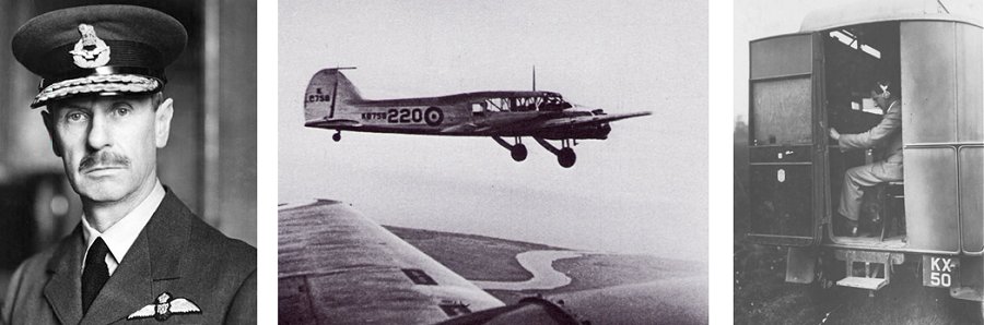
Figure 2.4 From left to right: Air Vice-Marshal Sir Hugh Dowding, the RAF Heyford bomber of the type that was the first Radar target in England in February 1935, Arnold Wilkins in the radio van that was used in the first Radar demonstration.
In order to preserve secrecy it was decided to erect the first Radar system not at Slough, but at a remote site at Orfordness. This was a remote split of salt marsh, already owned by the Air Ministry that could be reached by boat from Orford. The group of three complimented by George Willis - the technical assistant of Bainbridge-Bell - arrived at Orfordness on the 13th of May 1935. During the first weeks this small group worked like slaves to have the first system installed. The receiver and the cahode-ray indicator were basically identical to the set-up for detecting thunderstorms at Slough and were assembled by Wilkins and Bainbridge-Bell. The transmitter was of a completely new design and the responsibility of Bowen. It was basically a couple of NT46 valves, the highest transmitting power valves used by the British Navy, used in a push-pull arrangement. With the filament consuming some 20 amps at 20 volts and the anode voltage pushed to 12000 volts, the transmitter eventually reached an output power of 200 kilowatts. Within a month on Monday the 17th of June the first echoís from a Scapa flying boat were received from a distance of 17 miles.
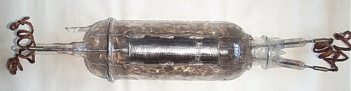
Figure 2.5 The NT46, the transmitter tube used in the first Radar experiments in Orfordness in May 1935. The valve measures 500x105 mm and nominally draws 40A of filament current at 15V and is rated at a maximum anode voltage of 10000V.
From that moment the progress was very rapid. Martlesham airbase assumed responsibility for the test flights for the new Radar system. With such flights on a daily basis, the performance of the equipment rapidly improved until it reached more than 100 miles in the early months of 1936. The successes in Orfordness prompted the Air Staff to ask for a set off five stations to provide air warning over the Thames estuary at the expense of a sum of £ 1000000. It was clear that this task was far beyond the capacity of the small staff at Orfordness so it was decided to increase the staff and to move to a more favorable site. Bawdsey Manor located not far from Orfordness at a location on the coast some 30 meters above sea level proved to be the ideal place. The Manor was purchased by the Air Ministry and in March 1936 the Radar group gradually took possession of the estate.
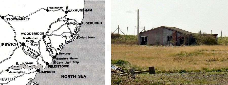
Figure 2.6 Map showing the Orfordness, Bawdsey and Martlesham area as it was in 1935. On the right, the receiver hut on Orfordness now.
Bawdsey Manor became an exceedingly busy place. The fast growing staff worked hard, often well after midnight. But there was also time for a swim before lunch or a game of cricket before dinner. The stimulating atmosphere has been compared to that of Oxford or Cambridge. Enormous 80 meter high antennas were erected and the white tower was converted in a laboratory. As the construction of the Radar stations proceeded, another vital component was added to the Radar scheme. The Tizard Committee, alert as always of the problems at hand, pointed out that it was not sufficient just to get a warning of approach of enemy aircraft. There was a need to coordinate the information coming from different stations, for decisions to be taken on which squadrons should be deployed against the enemy, and for precise instructions to be given to the fighters. When the final air defence system came into being it was as a result - in contrast the Radar systems in other countries - a fully integrated one. It consisted of the air warning network, a filtering process for assessing and collating the data and an efficient communications system for alerting the fighters and guiding them to their targets. The performance of the stations was so good that before the end of 1936 plans were made to extend the air warning network to a chain of 19 stations along the whole of the east coast, later to be extended by another 6 stations to cover the South Coast. The Battle of Britain could never have been won without ďHome ChainĒ as the Radar system was called by then. It was a tribute to the genius of Tizard who foresaw the problem, and to Watson-Watt who provided the solution.
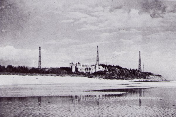
Figure 2.7 Bawdsey Manor, the headquarters of Radar research in Britain from 1936 until the outbreak of the war in 1939.
| to top of page | back to homepage |
The success of the integrated Home Chain Radar system prompted Tizard and his committee to start thinking about the next steps to be taken. Tizar argued that as soon as the RAF would have a better chance of repelling the German Bombers at daytime, they would undoubtedly increase their night bombing efforts. At night, the Home Chain Radar system was much less effective: the range at which an enemy aircraft could be seen was less than 300 m, and it was clearly beyond the capability of the Home Chain system to guide a fighter that accurate to its target. What was required was a Radar small enough to be installed in a night fighter, which would enable the pilot to close a range of 4 or 5 miles down to the required 150 to 300 m on his own initiative.
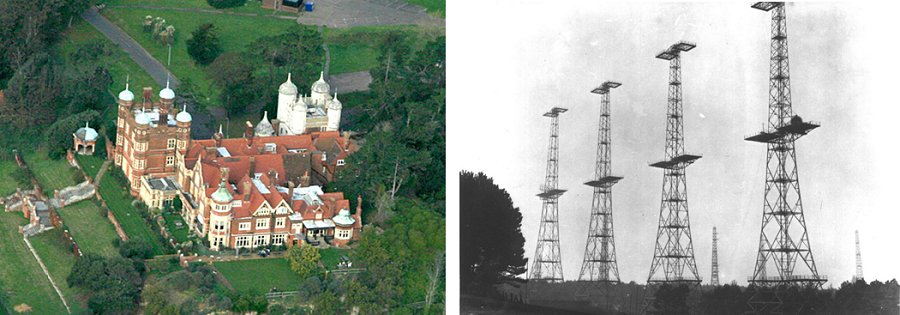
Figure 3.1 Left, Bawdsey Manor anno 2008 the red tower with the white tower behind it. Right, the transmitter towers at Bawdsey of the Home Chain system during World War II.
No one was very optimistic about the feasibility of such a miniature Radar system at that time. The original wavelength of the Radar system during the first trials in Orfordness was 50 meters (6 MHz). Watson-Watt had chosen this wavelength on the assumption that the best reflected signals from an aircraft would be on the wavelength at which the wing span acted as a dipole resonator. Since many bombers of that period had a wing span of about 25 meters, they would thus resonate at 50 meters wavelength. Due to interference with commercial traffic this wavelength was later reduced to 26 meters, and again later to the final wavelength of 10 to 13 meters. To achieve a reasonable antenna size for airborne systems however, the operating wavelength would have to be reduced to one or two meters (150-300 MHz), which was clearly beyond what was possible at that time. In addition, the pulse width had to be reduced from 20 to 1 microsecond, which was strictly unknown territory. On top of that the size and weight of the system had to be such that it would fit into an airplane.
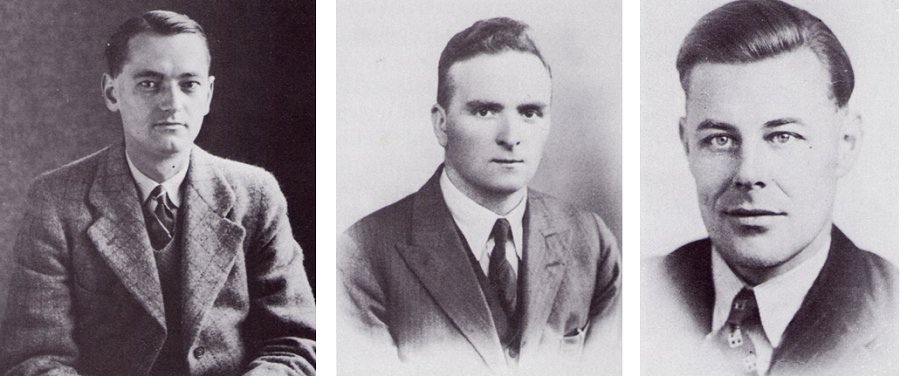
Figure 3.2 Left A.G. Touch, middle ĎPercí Hibbert and right Keith Wood members of the original airborne Radar team.
Despite all the obvious difficulties Bowen managed to persuade Watson-Watt to embark on the airborne project around mid-1936. A small team was formed consisting of Bowen, Gerald Touch, Sidney Jefferson and Perc Hibberd (Fig. 3.2). One of the most important designs restrictions for the airborne Radar system was that the antenna should not cause too much aerodynamic drag, eliminating any type of long wire antenna. The most that could be tolerated was a stub antenna, half a meter or so in length, demanding a wavelength of about a meter (300MHz). This was on edge of what was possible in 1936. In his book ďRadar DaysĒ Bowen recollects a striking story from this period:
| ĎAbout this time, we stumbled on a gem beyond price; it was a tuned radio frequency (TRF) receiver designed by EMI for their projected television service from Alexandra Palace. It operated on a frequency of 45 megacycles per second or a wavelength of 6.7 meters and had a bandwidth of 1 MHz. It had 7 or 8 valves on a chassis about 3 inches wide by 15 or 18 inches long. I cannot quote the sensitivity, but it was far and away better than anything which had been achieved in Britain up to that time. This receiver formed the basis of our whole airborne Radar experimental programme for the next two years. I have never discovered exactly how we came by that particular set, but I suspect it came through the back door of the EMI Company; they had no idea of the use to which it was being put. During the next few years we made strenuous efforts to obtain additional receivers of the same design; but although the negotiations were conducted by Watson-Watt himself, he failed to produce another chassis. This account being written some 50 years later and it is difficult to believe that until the end of 1938, when we had two Ansons and the Battles as experimental aircraft and at least a number of Radar transmitters to share between them, we only had the one receiver chassis which was switched from one aircraft to the other as occasion demanded!í |
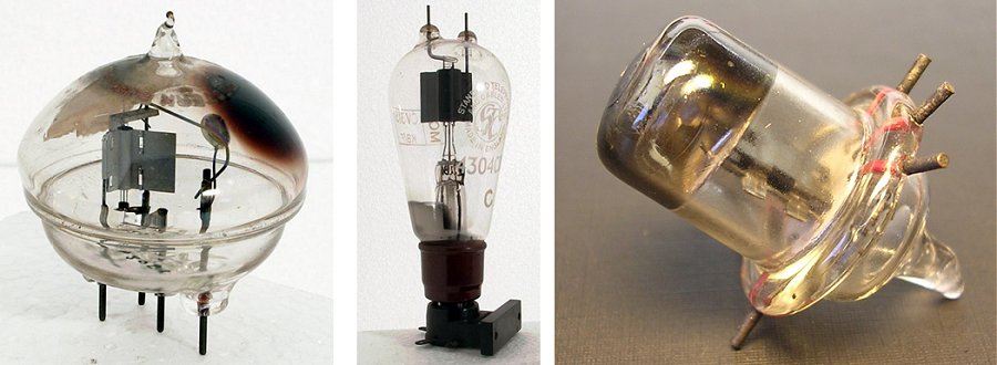
Figure 3.3 Left, the Western Electric 316A ďgiant AcornĒ or ďdoor-knobĒ valve that was used in the first 6.7 meter airborne Radar transmitter. Middle, the 4304 CB (alias NT58, VT62, CV2761). Right, an RCA Acorn tube that was used in the down converter of the first 1.5 meter Radar system.
Rapid progress was being made in the airborne group however, and by March 1937 Perc Hibbert had built a 6.7 meters transmitter using two Western Electric 316A ďgiant AcornĒ or ďdoor-knobĒ valves as they were called. Although the output power could not have exceeded a few hundreds of Watt at a pulse length of 2 to 3 microseconds and a repetition frequency of a 1000Hz, it enabled the first fully airborne Radar system with a detection range of three to four miles. The system was installed in the Heyford, and in March 1937 the first ground objects were detected during a trial flight. This success generated considerable enthusiasm and Bowen and his team were given free choice for an aircraft especially devoted to the airborne Radar program. They selected an Anson, and much to their surprise they were allocated not one, but two aircraft.
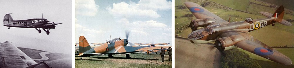
Figure 3.4 Left, the Avro Anson K8758 aircraft acting as target during the initial airborne Radar experiments photographed from the Radar equipped K6260. Middle, a Fairey Battle. Right, the Blenheim MK IV.
During the summer of 1937 Bowen and his team worked hard getting the wavelength of the airborne Radar system down. By converting the transmitter to push-pull operation using two 316As, they managed to reduce the wavelength to 1.25 meters at a pulse width of one microsecond. Below 1.25 meters the output power of the transmitter dropped sharply. Touch rebuilt the receiver to operate at 1.25 meter by converting it to a super-heterodyne, using acorn valves from RCA in a mixer stage ahead of the one and only EMI chassis. The latter became the IF-amplifier, still on its design frequency of 45 MHz. It is interesting to note that in this way the transmit frequency of the original Alexandra Palace television system of 45 MHz became the standard IF frequency for all airborne and many other Radar systems for the remainder of the war, and probably a long time afterwards! The 1.25 meters system was installed in one of the Ansons and on the first flight targets were detected. It was soon found that a small increase in wavelength to 1.5 meters (200 MHz) greatly increased the sensitivity. This was the moment that the 200 MHz Radar was born, which was to remain the most widely used frequency band for airborne, ship borne and ground based Radar during the whole of the war [8].
A few days after the successful demonstration of the 1.5 meter system, Bowen and his team were invited to take part in an exercise that was planned starting on the 4th of September (1937). The goal of the exercise was that Coastal Command would search for the British Fleet in the North Sea. The fleet would follow a zigzag coarse and, naturally would try to avoid discovery. A total of 48 aircraft, none equipped with Radar of course, since that was obviously still in development and highly secret, were scheduled to search for them. Bowen and his team in the Radar equipped Anson managed to find the fleet within a few hours. They were then overtaken by bad weather. With the help of their Radar they managed to find their way back safely. When they returned they learned that they indeed had spotted the fleet in the right location but also that the exercise had been cancelled due to bad weather. It was something of a landmark in the history of airborne Radar. They had found the fleet under conditions which had grounded Coastal Command, they had detected other aircraft for the first time with a self-contained Radar and, simply by returning home in one piece, had demonstrated some of its navigational capabilities. From then on their path was much easier and they were besieged for flight demonstrations, none the least for Sir Henry Tizard, for whom this was a particular nostalgic occasion.
Klick here to hear Keith Woodís verbal account of the exercise.
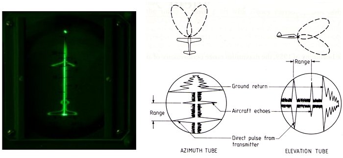
Figure 3.5 In the first Air Interception Radar systems, the location of the bearing and the elevation of the enemy plane was indicated on two separate oscilloscope screens.
By the end of 1937 the team worked on two projects Ė Air to Surface Vessel (ASV) and Air Interception (AI). Much of 1938 was actually spent on the development of the ASV system. During 1938, the principal instrumental improvement in the airborne Radar system was the substitution of Western Electric 4304 valves for the Ďgiant acornsí in the transmitter. They gave an increase in peak power to 1 or 2 kilowatts. In the course of 1938 the Anson aircrafts, which were becoming rapidly obsolete, were replaced by two Fairy Battles. Towards the end of 1938 it became clear that AI and ASV would soon come into service and the problem of how to supply them with electrical power became an important consideration. The standard RAF generator at that time was a 500 watt, 25 DC machine. Most of this power was taken up by the existing aircraft equipment and on top of that the Radar equipment was going to require such a variety of voltages that an alternating supply was essential. A way out was to fit an AC generator on the spare generator shaft of the second engine. The story how this generator came into service is an excellent example of prewar decisiveness and pragmatic engineering [10].
 Towards the beginning of 1939 it became clear that the ranging performance of the air-to-air Radar was more or less adequate. The most urgent task therefore was to add directional information in azimuth and elevation. After considering a number of alternatives it was decided to indicate bearing and elevation in the way depicted in Fig. 3.5. In total four antennas were used, two with overlapping antenna patterns for azimuth and two for elevation. The data was represented on two CRT tubes. The image on the CRT tubes showed the direct pulse from the transmitter and, at the far end, the reflection from the ground (the so called Xmas tree). The simulation on the left gives an impression of how an approaching aircraft would be observed by the Radar operator. A mechanical switch designed by Touch was used to multiplex the receiver and transmitter over the four antennas of the aircraft.
Following the Air Ministries decision to adopt the Benheim as a night fighter, an extensive series of flight trials using Blenheims K7033 and K7034 as night fighter and target respectively was began. In July 1939 things were rapidly coming to a head in Europe, and Bowen and his team had to start thinking about producing airborne Radars in quantities. Vickers was selected as a contractor for the transmitter but the receiver possed to be a greater problem. Unbelievably, Bowen and his men at that time still only had one receiver: the original 45 MHz EMI chassis. The most logical choice for a contractor would obviously have been EMI but Bowen was under some kind of restraint not to talk to them. Instead Cossor, who had built receivers for the Home Chain system, was asked to produce some 45 MHz receiver samples. They turned out to be a complete failure. They did not come within a tenth of the required sensitivity, and their weight was astronomical, weighing more than their complete system at that time. The receiver was rapidly becoming a problem!
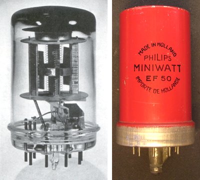
Quite by chance in April or May of 1939, Bowen heard some encouraging news from Edward Appleton, his old Professor at Kingís College and now the Jacksonian Professor of Physics at Cambridge. He told Bowen that the Pye company, still hoping that there would be a television industry in Britain, had set up a production line for 45 MHz chassis and had actually made a trial run! Bowen immediately went to Cambridge to see B.J. Edwards, the Technical Director of Pye, and was rewarded with a remarkable sight Ė he had scores of TRF chassis of just the type that they were looking for! The chassis was built around a revolutionary new tube, the EF50.
| to top of page | back to homepage |
What makes the EF50 special is that it was the first all-glass valve that was designed in such a way that it could be produced in very high volumes at low-costs. People have talked about the ďinvention of the EF50,Ē but invention is not really the correct term to be used here. The EF50 was merely one of the milestones in the development process of radio tubes that started in the mid thirties, and eventually ended in the miniature Noval radio tubes we are all so familiar with. After the invention of the triode, the manufacturers of incandescent light bulbs were the obvious candidates to take this new invention into mass production. Like the incandescent light bulb, the radio tube also required a vacuum glass envelope, a filament and wires sealed into the glass envelope. By the end twenties highly automated production lines for the production of incandescent light bulbs had been developed, and it was only natural that those machines and techniques were adopted for the fabrication of radio valves.
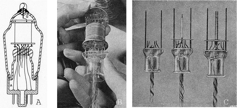
Figure 4.1 The glass pinch which formed the base for tubes developed in the twenties and thirties.
These early radio valves were all based on what is called ďa pinch.Ē The pinch is the central part of the tube were the lead-in wires are fed through and which mechanically supports the electrode system. Figure 4.1 schematically shows a cross-section of a valve manufactured in a pinch based technology and it shows some photographs of glass pinches together with the glass exhaust tube.
The fabrication sequence of the pinch based tubes starts with the cutting of pieces of glass tube. On one side of the glass tube a small collar is formed by heating the edge and pressing the tube against a conical shape (Fig. 4.2b). Next the other side of the glass tube is turned into a more or less rectangular opening by heating it and opening it with a V-shaped pair of pliers (Fig. 4.2e).
Next the electrode bases and the rods that support the electrode assembly, together with the glass exhaust tube are placed in a fixture/mold which exactly positions these parts with respect to each other (Fig. 4.3a). The lead-in wires are already attached to the electrode bases at this point. The pre-formed glass pinch is placed, top side down, over this assembly. The glass pinch is heated at the narrowest point, and closed by pressing with an anvil (Fig. 4.3c). A small opening to the exhaust tube is formed by heating the glass pinch with an extremely sharp pointed flame, while at the same time some compressed air is applied to the exhaust tube (Fig. 4.3d). This will form a glass bubble which at a certain point will burst open forming the opening (Fig. 4.3e). The whole fabrication sequence is beautifully recorded for posterity by OSRAM.

Figure 4.4 Cutting of glass tubes for the pinch (left) and sealing of the electrode wires in the pinch with the anvil (right).
The pictures are stills from the OSRAM movie Manufacture of Modern Radio valves, 1930.
The pinch technology, borrowed from incandescent light bulb manufacturing, made it possible that radio could be taken quickly into high volume production. However, within a few years also the limitations of the pinch technology became apparent:
 Figure 4.5 Metal valve envelopes developed in the thirties as an alternative for pinch based valves.
To find a way to make radio valves better suitable for high frequency operation, valve manufacturers in the thirties came up with the concept of the metal valve. The first one in this series was the CATKIN (diminutive of Cooled Anode Transmitter). It was developed by G.E.C. in Britain and was derived from metal transmitter tubes, in which the metal envelope was used as the anode connection (Fig. 4.5A). The CATKIN was expensive to manufacture and it was not a success. The CATKIN was only manufactured for a few years.
In 1934 G.E.C. in the US introduced another metal tube concept (Fig. 4.5B). It consisted of a metal base plate (the heather) into which ďFernicoĒ (iron-nickel-cobalt) eyelets, each one containing a hard-glass bead with a lead-in wire, were welded. The lead-in wires were welded to pins which were pressed in a Bakelite bottom plate in octal-base configuration. After the electrode system was mounted, the iron envelope was welded to the header by means of a very heavy projection welder. Klaas Rodenhuis vividly remembers the enormous ďbangĒ produced by these welding machines when they welded the envelope to the header. The tube was exhausted through a metal tube welded to the header. Philips second-sourced these valves in high volumes for the foreign market straight through the war. The valve did have lower parasitic capacitances and inductances, but was also expensive to manufacture.
In 1935 R.C.A. developed a variant of this model of which it was hoped that it would be less expensive as the construction described in the previous section. In this tube the metal header was replaced by a glass plate with sealed-in lead wires (Fig. 4.5C). Both this tube, as well as the previous tube used a top control-grid connection. Everybody was so used to the top grid connection that another construction was simply not considered. Telefunken surprises everybody, when in 1937 they introduce a single ended all-metal valve, the so called ďStahlrŲhreĒ (Fig. 4.5D). In this valve all connections were located on the bottom side of the tube, which obviously meant a big advantage for set-makers. The electrode system in this tube was horizontally, which implied a better mechanical stability, and less microphony. It did however imply a rather large tube diameter which reduced the inter-electrode capacitances, but didnít help in reducing the size of receivers. In inter-electrode capacitances were further reduced by the way the pins were grouped (in groups of 3 and 5 opposite of each other) and by the placement of metal screens between the electrodes in the tube. Technically the tube was superior, but the implementation was again expensive because of the use of ďFernicoĒ eyelets.
| to top of page | back to homepage |
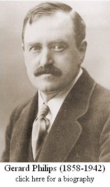
Philips entered the radio-tube arena relatively late. In most European Countries the First World War had been a driving force behind the development of a solid industrial base for these new components. But, since Holland was neutral during the First World War, Philips had deployed little or no initiatives in that direction. Gerard Philips, the founder of Philips, didnít think much of these new gadgets. As far as he was concerned, they were a plaything for the military and the post offices,
 and they held no promise for high volume production, and that was just the thing Philips had specialized in.
Philips was founded by Gerard Philips in 1891. Gerard came from a family of entrepreneurs. His father was a banker, but he also ran a tobacco trading company, a coffee roasting company a cotton mill and he owned a gas factory! Gerardís interest was however more in technology. In 1883 he graduated from the faculty of Mechanical Engineering in Delft, and a few years later supervised the installation of electrical light on the Dutch steamer ďPrince Willem of OrangeĒ in Glasgow. During this trip to Scotland he came into contact with the famous physicist Thomson. He stayed with Thomson for a year, and during that period learned everything there was to learn about electricity. Back in Holland, Gerard developed
 his own technology for making light-bulbs. With financial support from his father he bought a small factory in the picturesque country village of Eindhoven, and in 1891 the private partnership ďPhilips & CoĒ is founded.
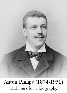
The first years are not easy for Philips. Fierce competition amongst light-bulb manufacturers forces Gerard to lower prices and increase production. Gerard then makes a clever move, being himself more an engineer than a business man, he makes his younger brother Anton a co-director responsible for the business aspects of the company. Together they form a golden pair in which Anton tries to sell more lamps than his brother can produce and vice versa. Business thrives, and across the road of the old factory new immense buildings are erected and Philips grows at an enormous pace. In 1900, less than 10 years after its foundation, production reaches 3 million light bulbs a year, making Philips one of the largest light-bulb manufacturers in the world!
By 1910 the number of employees has reached 2000. Philips is now the largest private employer in Holland. Then, an unexpected event upsets the otherwise so peaceful life of the two brothers. Within a time frame of a few years, General Electric introduces two innovations: ductile ďpulledĒ tungsten filaments and gas filed light bulbs. The engineers in Eindhoven are completely taken by surprise, and Philips is forced to buy the required equipment and licenses. The technology is quickly introduced, and within no time the Philips Argon filled lamps even prove superior over the lamps of G.E.
Gerard and Anton realize that the innovations from General Electric were the result of fundamental physical research. In the mean time, the number of employees of Philips has grown to over 3500, and the company is about to celebrate its 25th anniversary. The brothers recognize that for the future of the company it is vital that Philips embarks on its own fundamental research program, so an advertisement for a scientist with a PhD in Physics is placed in the newspapers. The scientist will be responsible for the setting up of a research organization that will make Philips less dependent on patents from others, and that will generate new ideas for products.
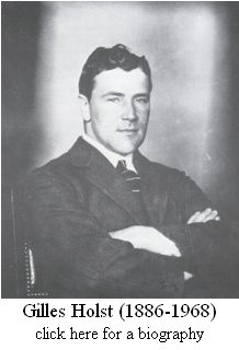 Among the applications they receive is one from Gilles Holst. Holst did his PhD under professor Kamerlingh Ohnes, who ran the low temperature lab in Leiden. Ohnes was the first to liquefy Helium and to discovere super conductivity in mercury for which he received the Nobel Prize for Physics in 1913. After a short interview Holst is hired, and he sets about organizing his lab. In 1914 Philips Research, or the ďNatLabĒ as it is known in Eindhoven, is founded. ďNatLabĒ being an abbreviation for ďNatuurkundig Laboratorium,Ē or Physics Laboratory.
Holst starts his new job by investigating the state-of-the-art in electrical lighting and all of the aspects related to it. The results of his study are published in a small book titled ďLichtbronnen en hare eigenschappenĒ (ďelectrical light sources and their propertiesĒ). He concludes that it was already too late to carry out fundamental research on incandescent light. The time was ripe to work on a new source of electrical light: the discharge tube. Discharge tubes were still something very new and fancy in 1914. Even the glow discharge itself was a phenomenon which was still poorly understood at that time. Philips Research would play an enormous role in the understanding and application of gas-discharges. The Tungsten Arc Lamp, the high pressure mercury and sodium lamps, the fluorescent light tube, cathode sputtering, impurity gettering, the theory on discharges in gas mixtures are but a few of the innovations originating from Philips Research in the period between the two World-Wars.
Then, on a quiet summer evening in august 1917, in the middle of the First World war, a small German Seaplane makes an emergency landing in Dutch territorial waters in the north of Holland. When the Dutch military officials salvaged the plane, they discovered something that surprised them: a radio receiver. As it turned out, it was quite an advanced radio because it used two EVN 94 vacuum tubes from Telefunken, switched in cascade! Understanding the potential of it for modern warfare, and facing an uneasy post-war relation with Belgium, the military officials commissioned Captain De Blauw to construct a number of similar radio sets. For the necessary radio tubes Captain De Blauw naturally turned to the largest light-bulb manufacturer in Europe, Philips. So Captain De Blauw sets about to make an appointment with Gillest Holst. As it happens, this is the start of a remarkable chain of events. Holst politely receives him in Eindhoven and listens to his story and request for help in the fabrication of radio tube samples. Undoubtedly, Holst must have been fascinated by these new gadgets and the physics that made them work. However, Holst also knew that Gerard Philips considered radio and radio-tubes a plaything for the military, and something with little practical and commercial value! Holst finds it difficult to do something that might upset his boss only three years after being appointed, and although tempted, he reluctantly turns down Captain De Blauwís request for help. Disappointed, Captain De Blauw turns to one of the dozen or so other light-bulb manufacturers in Holland: ďde MetaaldraadlampenfabriekĒ in Utrecht. They are quite willing to help him, and a few weeks later the first radio-tubes manufactured in Holland are delivered to Captain De Blauw.
In the development of radio into something as we know it today, radio amateurs played an important role. The ending of the War, during which listening to radio was forbidden, gave an enormous impulse to the popularity of radio amateurism. But what to listen to? Most radio transmissions where in Morse code originating from post offices, news agencies and of course the odd spy. Transmission of speech, let alone music, was practically unheard of. This was something that troubled the
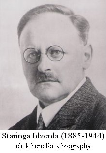 Dutch radio pioneer ďHanso Henricus Schotanus ŗ Steringa Idzerda,Ē a long and difficult to pronounce name, even to Dutch standards. Idzerda, was an electrotechnical engineer and a keen radio amateur. Already during the war Idzerda run a small wireless instruments and consultancy agency from The Hague, mainly servicing the military. After the war, Idzerda changed the name of his company to ďNederlandsche Radio-Industrie.Ē It is his dream to build and sell radio receivers to ordinary civilians. Since there was basically nothing to listen to, he intends to provide the buyers of his radio sets with interesting programs consisting of news, music and radio plays transmitted from his company in The Hague.
To realize his ambition, Idzerda needs a steady supply of radio tubes. So naturally he first turns to the ďMetaaldraadlampenfabriekĒ in Utrecht, who a year earlier had provided Captain De Blauw with radio tubes. They are however unable to supply him the tubes because they have signed a ďcontract of secrecyĒ with the Ministry of War. Idzerda now turns his hope to Philips. One way or the other, he is able to convince Gerard Philips himself of the economical significance of his vision, because Gerard orders Holst and his staff to fabricate the tubes according to Idzerdaís specifications. The tubes are advertised under the name ďIDEEZET-lamps,Ē and in an advertisement in ďRadio NieuwsĒ of January 1919, Idzerda proudly announces that already 1450 tubes have been sold.
Following instructions from Idzerda, Philips also manufactures several transmission lamps. In August that year the first transmissions take
place from Idzerdaís radio station, which transmits with less than 20
 watts of RF power, and is heard within a radius of 60 km around ďThe Hague.Ē On the 5th of November 1919, Idzerda places an advertisement in the news papers, announcing a ďSoirťe-MusicaleĒ for the following Thursday between eight and eleven. It is a world-premiere, since it is the first radio broadcast which is preceded by an announcement of the program in the news papers. The event is internationally recognized as the birth of public radio broadcast.
In the following years, the fabrication of receiver tubes remains a relatively insignificant activity compared to the fabrication of light-bulbs. This is however not the case for X-ray tubes and transmission tubes. There, a stroke of luck places Philips in ideal position. In the early years of 1920, Holst visites one of the glass-blowing factories where light-bulbs are being fabricated. He notices that some of the glass-blowers have more difficulty in removing the light-bulb from their blow-pipe than others. He finds this intriguing, and decides to investigate the cause. He discovers that when the blow-pipes are made from a particular chromium-iron alloy, they have an almost perfect adhesion and thermal match to the glass. The story goes that Holst after founding the cause, immediately rushed to the patent department and got the discovery patented. The patent indeed proved of immense value to Philips. It allowed them to make powerful transmission tubes with a water cooled anode and the so called ďMETALLIXĒ X-ray tube which was partly made from metal to reduce stray radiation.
Finally, in 1923 the idea of public radio broadcasts really sets of and the demand for radio tubes explodes. Tube manufacturers are hardly able to supply the demand, and Philips quickly changes gears. After the fabrication of light-bulbs was moved to a location just outside the center of Eindhoven, the huge plant on ďde EmmasingelĒ (Fig. 6.2) became available for the production of radio tubes. Whereas in 1921 only 320 radio tubes were fabricated in total, in 1923 the production had increased to 1000 tubes a day!
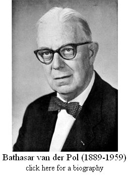
In 1922 Gilest Holst hires the Dutch Scientist ďBalthasar van der PolĒ to head the research and development of radio tubes. Van der Pol who had worked under Thomson and
Fleming in England was a brilliant scientist who already in 1917 in ďWireless WorldĒ had featured in an article ďPersonalities of the Wireless World.Ē Van der Polís first job was to work on oxide coated filaments. So far just normal tungsten filaments had been used in radio tubes. To get sufficient electron emission, these filaments had to be
 heated white hot, so that these tubes were cold ďhel brandersĒ or ďbright burners.Ē In fact the radios in those days gave as much light as sound. To save batteries and tubes, van der Pol and his staff developed barium and thorium coated filaments. The low work function of these materials strongly increases the electron emission of the filaments, so that they could burn at lower temperatures. Philips successfully introduced these tubes in 1924 under the brand name ďMiniwatt.Ē At that moment already 9 out of the 16 researchers at Philips were working on radio tubes.
In 1924 Bernard Tellegen joins the radio tube research group of van der Pol. He is then 24 years of age and has only just graduated. He was put on a very practical problem: due to new safety regulations, the anode voltage in radio receivers was limited to less than 250V. At these low
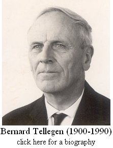 voltages it was difficult to generate enough output power for a loud speaker with a simple triode. The triode had namely two serious drawbacks. First of all it didnít behave like a current source, in other words, the anode current not only increased with increasing grid voltage, but also with increasing anode voltage. This seriously limited the maximum amplification and the output power of the tube. At the same time there was a strong capacitive coupling between the anode and the grid. This Miller capacitance limited the high frequency operation. In 1915 a remedy to these drawbacks was found by Walter Schottky. By inserting a screen grid in between the control grid and the anode, which was held at a constant high potential, the anode potential is effectively screened from the control grid. In its hybrid form this arrangement is of course still widely used, and is known as a cascode. The tetrode as is was called, represented an enormous improvement, but in its turn also had a drawback. Electrons accelerated by the high potential on the screen grid bombarded the anode and generated secondary electrons. Unfortunately, in operating conditions where the anode voltage is low compared to the screen grid, these secondary electrons are accelerated to the screen grid, causing a current flow in the opposite direction. The result is a kink in the anode current characteristics. The problem especially occurred in output stages where the output voltage would swing between supply voltage and almost zero. Tellegen studied the problem, and came up with a very simply solution. He simply inserted a third grid between the screen grid and the anode. This brake- or suppressor grid was
 connected to a low potential e.g. the cathode. The suppressor grid simply pushed the secondary electrons back to the anode and all at once the disadvantages of the tetrode had disappeared. The pentode was a near ideal amplifying device with very high amplification and capable of delivering high output powers at relatively low voltages. Tellegen and Holst immediately applied for a patent on the 14th of December 1926. It turned out to be perhaps the most valuable patent of Philips ever. In 1932, little more than 10 years after the first samples were made in the research lab, Philips produced its 100 millionthís radio tube.
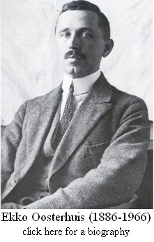
The popularity of radio increased explosively, and it had not remained unnoticed by Anton Philips that, whereas the price of a radio tube on average was 10 guilders, the price of a complete radio was about 200 guilders. So obviously making radio sets was a very profitable business. This, combined with the fact that Philips now had their hands on a superior radio tube, the pentode, made them feel confident enough to start thinking about producing radioís themselves. For Philips in 1926 this was something of a revolution. So far Philips had been a component manufacturer. A radio was a system, and manufacturing a system would require a completely different approach! From the onset it was clear that the receiver had to be suitable for mass-production, it should be reliable, easy to use, of high quality and reasonably priced. Holst discussed the issue with Van der Pol. Van der Pol personally had no interest in the development of domestic receivers, although some members of his group were very active in such development. Holst understood the situation and rather than putting pressure on Van der Pol to turn his attention to something he disliked and possibly even despised, Holst asked Ekko Oosterhuis to ensure that a commercial radio set was developed
 quickly. So Oosterhuis set up a ďpractical radio groupĒ which got on with the job. The solution of Holst was exemplary for the style of management at Philips Research which was always aimed at creating a working atmosphere that would get the best out of people. For a time the group of Oosterhuis was in competition with the group of Van der Pol. The group of Oosterhuis concentrated on so called ďStraight Receivers,Ē while Van de Polís group concentrated on ďHeterodyne ReceiverĒ configurations. Visits were paid to RCA in the US to study mass production. A thorough study was made on how something so complex as a radio could be made on a large scale with a high accuracy and yield by unskilled hands. The result was the 2501, in Holland nick-named ďthe loaf of bread.Ē Because of the high gain of the pentode, only three radio tubes were needed compared to four in radios from competitors. It was an enormous success. In 1927, 6000 receivers were built; in 1930 the production had already increased to half a million radios a year.
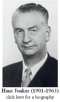
Johan Lodewijk (Hans) Jonker was born the 19th of March 1901 in The Hague. He studied electrical engeneering in Delft. For several years he headed the radio tube development group at Splendor, one of the smaller radio-tube manufacturers in Holland.
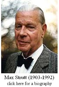
 In January 1930 Jonker joins the radio research group of Ekko Oosterhuis at Philips Research. His fellow group members include: Tellegen, the theoreticians Strutt and Aldert van der Ziel who became famous because of his work on noise. By the time Jonkers joined Philips, the development and
production of radio tubes had grown to such an extent, that it was felt necessary to organize a separate radio tube development and application laboratory close to the production site. In this way the research groups could concentrate on more fundamental issues. Jonker is assigned to the task to organize this Lab, and on the first of November 1931 he leaves
Philips Research to found and organize ďthe Jonker Lab (Radio IV)Ē on the fourth floor of the radio tube production plant on the Emmasingel. This lab, which later became known as the ďbuizenlabĒ (the tube-lab), would become the birthplace of virtually all the tubes which would make Philips the largest tube manufacturer in Europe. On the 19th of September 1936 Jonkers returns to Philips Research to head the radio tube research group.
In January 1930 Jonker joins the radio research group of Ekko Oosterhuis at Philips Research. His fellow group members include: Tellegen, the theoreticians Strutt and Aldert van der Ziel who became famous because of his work on noise. By the time Jonkers joined Philips, the development and
production of radio tubes had grown to such an extent, that it was felt necessary to organize a separate radio tube development and application laboratory close to the production site. In this way the research groups could concentrate on more fundamental issues. Jonker is assigned to the task to organize this Lab, and on the first of November 1931 he leaves
Philips Research to found and organize ďthe Jonker Lab (Radio IV)Ē on the fourth floor of the radio tube production plant on the Emmasingel. This lab, which later became known as the ďbuizenlabĒ (the tube-lab), would become the birthplace of virtually all the tubes which would make Philips the largest tube manufacturer in Europe. On the 19th of September 1936 Jonkers returns to Philips Research to head the radio tube research group.
So the research and development of radio tubes took place on two places: the research lab at the Kastanjelaan and the tube-lab on the Emmasingel. Besides these, there were smaller development centers at the production sites. The group in the Research Lab concentrated on more fundamental
 issues, such as secondary emission and the calculation of electron trajectories. Sometimes this resulted in innovative new tubes and concepts such as the EE50 secondary emission television tube and the
remarkable E1T Counting Tube,
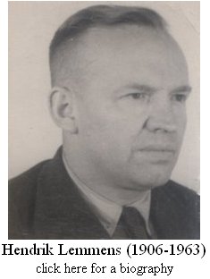
which were not necessarily always a commercial success. In any case the research group was equipped with all the manufacturability capabilities to make their own radio tube samples. Especially the glass blowing and crafting capabilities were renowned. This department was headed by the eccentric Lemmens who contributed to many inventions, such as the powder glass tube bases, the L-cathode and high pressure gass-discharge tubes.
issues, such as secondary emission and the calculation of electron trajectories. Sometimes this resulted in innovative new tubes and concepts such as the EE50 secondary emission television tube and the
remarkable E1T Counting Tube,
which were not necessarily always a commercial success. In any case the research group was equipped with all the manufacturability capabilities to make their own radio tube samples. Especially the glass blowing and crafting capabilities were renowned. This department was headed by the eccentric Lemmens who contributed to many inventions, such as the powder glass tube bases, the L-cathode and high pressure gass-discharge tubes.
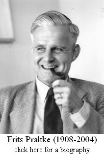
The tube-lab on the Emmasingel mainly consisted of two groups: the ďSamples DepartmentĒ (
Proefafdeling) of Dr. Frits Prakke and the ďElectrical LaboratoryĒ of ir. Gerrit Alma. The samples department could manufacture all the parts
necessary to make tubes, as well as small series of complete tubes. The department also developed new processes and provided assistance in
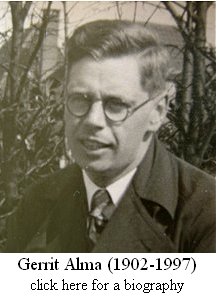 solving problems with fabrication processes. Cathode poisoning was such a reoccurring problem. After much research it was found that small contaminations, specifically traces of chlorine could ďpoisonĒ cathodes, resulting in early failure. An interesting anecdote is that this knowledge was used to sabotage the production of tubes for the Germans during the Second World-War. A small cylinder of chlorine gas, hidden on the roof of the building, was used to add minute and undetectable traces of chlorine to the vacuum of the tube. Although these tubes tested ok when they left the factory, they failed after a short period of use. The scheme was never discovered by the Germans. In the electrical laboratory of Gerrit Alma, designs for new tubes were made which were subsequently fabricated by the sample department. When the tubes samples came back they were tested and evaluated. The electrical laboratory was also responsible for the development of the required test equipment and procedures. From early 1939 onward all development and manufacturing of radio tubes fell under Dr. Tromp, who played an important role in the flight of the EF50 to Brittain.
The fact that the samples department of Dr. Prakke and the electrical laboratory of ir. Alma were two separate organizations, resulted in many misunderstandings, frictions and delays. An example is the development of
the all-glass valve (see next section).
 Shortly after the war Prakke was promoted to head the television picture tube development, and both departments are united under Alma. The sample department, now called the technology group was led by van Tol, a former production chief, who leads this group very skillfully.
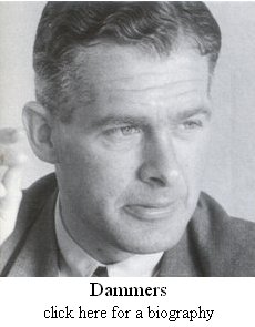
Again a few years later, the electrical laboratory is split into what we what now would call consumer devices: ďRadio Receiver TubesĒ (Radio Ontvangbuizen) headed by Dr. Dammers, and the group ďProfessional Receiver
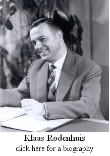 TubesĒ which was trusted to ir. Rodenhuis. In subsequent further reorganizations more groups were added to the radio lab of ir. Alma. Rodenhuis remembers Alma as a very pleasant and skillful boss. Later when Rodenhuis had become the director of the Philips tube division in Hamburg ďValvoĒ, he realized how much Alma had shielded his groupleaders from administrative burdens.
The Professional Tube group of Rodenhuis was in a sense a continuation of the ďshort-waveĒ group he had led earlier. The group had in the mean time developed a triode that could generate signals up to 1 GHz (EC80, EC81). A new task for the group was the development of receiver tubes with an improved reliability and expectancy for industrial applications. After an analysis of the factors which
determine the reliability and life of normal tubes, the construction, materials and production processes were optimized resulting in significantly more reliable components. In particular it was found that small particles negatively influenced the reliability, so Rodenhuis was the first to introduce glove boxes for the production of tubes. These
Special Quality tubes can easily be recognized from the tube designation: E90CC and E82M are e.g. the Special Quality variants of the ECC90 and EM82. These tubes were used in measurement equipment, computers (e.g. for IBM who was their biggest customer) and transmitters. An example is the famous EC56 ďlighthouse triodeĒ which contained the L-cathode invented by Lemmens which was used in most of the European microwave link
 transmitters and which was so robust that there was virtually no replacement market.
The Radio Tube Application lab was at that time headed by Dr. Dammers, and was often referred to as the ĎDammers LabĒ. Dr Dammers who joined Philips in 1945, was the author of several books on radio tubes. His exceptional insight into radio tubes is legendary, and he was the father of many radio and television circuits. The tube application lab designed and tested application circuits for the tubes that Philips manufactured. In this way it bridged the gap between the tube development and production division and the television and radio set-makers, both in and outside Philips. Ir. Hoefgeest remembers how during a presentation in
Scandinavia of the Application Lab not less than 49 television set makers from Scandinavia alone attended (39 in Spain)! In 1963 the name was changed to CAB (Central Applications Laboratory Building blocks) when the Electron Tube and ICOMA Industriele COmponenten en MAterialen = Industrial COmponents and Materials) divisions were merged to become the ELCOMA (Electronic Components and Materials) division. Contacts with internal customers was intensive from the very beginning. The RGT (Radio, Gramophone and Television) Division, now part of Consumer Electronics, was one of the biggest customers. The arrival of the transistor and the IC shifted, to a large extend, the focus to the design of television ICs. In 1967 the Application Lab was relocated from the building on the Emma Singel to building BA at the ďBeatrix SiteĒ also in Eindhoven, where it remained until July 2002, when it was moved to buildings A320 and A410 on the High-Tech Campus in Eindhoven.
| to top of page | back to homepage |
The first publication known to me refering to the new all-glass tubes was a conference proceeding by M.J.O. Strutt from the tube development group at Philips Research [25]. The presentation was given at the first ďInternationale Fernseh-Tagung in ZŁrichĒ (international television conference in ZŁrich) held from 19 to the 21th of September 1938. The paper discusses several aspects of ďstraightĒ receivers for television. To illustrate the latest developments in the design and fabrication of high performance radio tubes, Strutt included a few photographs of the new all-glass Philips valves (the EE50 secondary emission tube in this case) (Fig. 6.4 A1 and A2) and a photo of a Telefunken ďStahlrohre.Ē Interestingly, in the acknowledgements Strutt specifically mentions the principle people involved in the development of these new tubes: G. Alma, J.L.H. Jonker and F. Prakke (Fig. 6.1).
Figure 6.1 First publication with a reference to the new all-glass tubes under development at Philips [25]. In the acknowledgements the men behind the development are identified.
A few months later, Jonker publishes an internal Philips Research Technical Note, Titled: ďNew radio Tube Constructions.Ē [21] (The original Dutch text of this report is available for download, as well as a translation of the relevant section into English). Indeed Jonkerís role in the development of the all-glass valve is confirmed by the head of radio valve manufacturing and development of Philips at that time: Th.P. Tromp. In a letter of Th.P.Tromp, head of the Radio Valve Department, to Mr. Bell dated 16th of Jan 1979 he writes [20]:
| The facts are these: Prof. Dr. Jonker (head of development lab of electronic valves in the mid thirties) was the originator of the EF50 and this development started already as far back as 1934/1935. It was indeed developed in view of possible television application. |
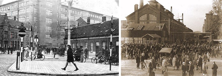
Figure 6.2 The two locations were the development of the all-glass valve took place: The tube development lab on the Emmasingel (left), and the glass factory on the ďGlaslaanĒ (right) both locations are in Eindhoven.
Jonkerís Technical Note gives a summary of recent radio valve developments [21]. Section two of the document briefly summarizes the first steps at Philips towards the all-glass valve:
| The introduction of the familiar ďacornĒ or ďbuttonĒ valve was at that time reason for us to revive an old idea, namely to try to eliminate the pinch in our old glass valves, since the length of the pinch often amounts to more than half of the total length of the valve. Since we had to accommodate the normal E-system in this new tube, we made a large type of button valve that would fit into a P-base [Ct8 base]. The grid was connected to the top of the tube through the exhaust tube to which a metal cap was cemented. |
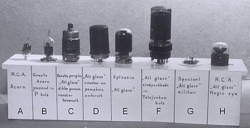
Figure 6.3 Detail from a photograph in the Technical Note by Jonker. Translation of the text: B. Large Acorn in P socket, C. First Press-Glass ďAll-glassĒ Thick pins and grid top connection, D. ďAll-glassĒ grid and exhaust tube on the bottom, E. Sylvania ďAll-glassĒ, F. ďAll-glassĒ power pentode in Telefunken socket, G. Special ďAll-glassĒ military. The original photograph is kept at the Philips Company Archive. Klick here for a full scan of the photographs.
Very interesting is the reference and photograph (Fig. 6.3 B) in Jonkers Technical Note to the ďlarge acornĒ with P-base (also known as Ct8 base).
Due to manufacturing difficulties, this tube was never commercialized.
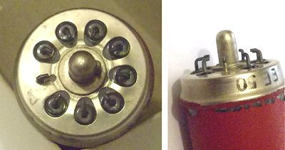
I had personally given up all hope of finding more information about this all-glass P-base until I received an email from Adri de Keijzer after the publication of this page. On a open air booth-sale some 15 years ago he actually found several all-glass P-base development samples in a box full of ordinary (Philips) tubes (Fig. 6.4). What a treasure to find!
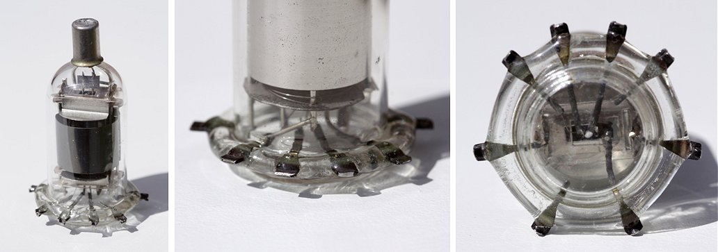
Figure 6.4 Development samples of the all-glass P-base tube. The pictures are by Adri de Keijzer who owns there rare samples.
Click here for more detailed photographs and a description.
The P-base was a typical Philips/Mullard base, and although it was in use for more than a decade, was not a technical success. The reliability of the contact of the tube to the socket was bad as well as the socket itself. This pushed the development in the direction of the pressed-glass valve base. Jonker:
|
Pressed glass is cheap, and if we could succeed in mechanically pressing the leads into the glass base, this would result in a cheap solution. After many experiments in the glass factory it appeared that thick Chrome-iron pins that could be directly inserted into a tube socket resulted in many problems. The bases cracked, or leaked. The lead-in wires had to be thinner and after some experiments the familiar bend pins that we know today were developed. This construction became possible after we decided to use a spigot which had been so successful in the American Octal Base valves. In this way the pins were protected against bending. When in the mean time all-metal valves were fabricated with all connections on one [bottom] side, we also investigated if something similar would be possible in the all-glass valve. Although this did not seem likely because of the thick glass bottom plate (capacitances), it nevertheless appeared to be possible by using effective screening. With the elimination of the top connection, it was no longer possible to hide the exhaust tube underneath the metal cap. We looked for a construction method whereby the exhaust tube could be fabricated on the bottom side. A method was found whereby a hole was made in the glass bottom plate onto which a glass exhaust tube could be molted. By placing a small metal box around the bottom part of the valve, on the base called ďthe metal trouser,Ē the exhaust tube could be neatly concealed, while the pins protruded through openings in this box. |
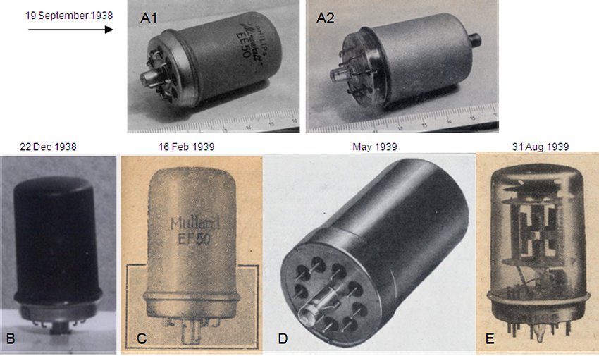
Figure 6.5 The earliest known photographs of the EF50/EE50 tubes using an all-glass envelop: A, Internat. Fernseh-Tagung Zurich 19 September 1938 [25], B. Philips Research Technical Note No. 1350 22 Dec 1938, C. The Wireless World February 16th 1938 [17], D. The Wireless Engineer May 1939 [18], E. The Wireless World 31st August 1939 [19].
The development of the final all-glass envelope clearly went through a number of stages. By reviewing the early publications and reports, it becomes possible to reconstruct the development states of the pressed- all-glass base (at Philips):
 too much pressure on the thin pins. The appearance of the spigot with the rim resembled a key, and hence these tubes were nicknamed ďsleutelbuizenĒ (keytubes). In the mean time the competition had started to introduce so
called ďsingle-endedĒ tubes, e.g. tubes with all connections on the bottom side, eliminating the need for a top-contact.
The relatively large distance between the pins in combination with the carful placement of metal screens inside the tube made it possible to relocate the grid to the bottom side without introducing additional feedback capacitance. Since the top contact had also been used to hide the exhaust tube, it was decided to relocate the exhaust tube to a position at the bottom of the tube where it would be protected by the ďmetal trouser.Ē The tubes in this state have thin bended pins and have either the exhaust tube or the grid contact at the top of the tube (Fig. 6.5 A2)
too much pressure on the thin pins. The appearance of the spigot with the rim resembled a key, and hence these tubes were nicknamed ďsleutelbuizenĒ (keytubes). In the mean time the competition had started to introduce so
called ďsingle-endedĒ tubes, e.g. tubes with all connections on the bottom side, eliminating the need for a top-contact.
The relatively large distance between the pins in combination with the carful placement of metal screens inside the tube made it possible to relocate the grid to the bottom side without introducing additional feedback capacitance. Since the top contact had also been used to hide the exhaust tube, it was decided to relocate the exhaust tube to a position at the bottom of the tube where it would be protected by the ďmetal trouser.Ē The tubes in this state have thin bended pins and have either the exhaust tube or the grid contact at the top of the tube (Fig. 6.5 A2)
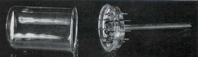
Figure 6.6 The balloon and the pressed glass base of the first all-glass valves (C-technique / Loctal-9 / B9G).
| Mid 1937, during a meeting with the board of directors, I have pointed out that there was something fundamentally wrong with the development of radio tubes. In particular the pace of development was too slow, and there was a lack of new innovative ideas which inevitably would result in losing our leading position. Two and a half years later, near the end of 1939, in a similar meeting I reminded the board of the previous meeting and I pointed out that in the mean time the organization had not changed, and that the situation was exactly the same as in 1937, only that now indeed we had lost our leading position. It is a fact, that since the invention of the pentode not a single new idea of any significance has been taken into production, and that any new idea of any significance lost its value because of the suffocating slow pace of development. The most notorious example is the development of the all-glass tube which, although it no doubt originated from Philips, took no less than 5 years. By that time others had preceded us. The situation had became so problematic that we can say in retrospect that outbreak of the war has saved us for a very painful situation. Telefunken had developed a metal tube of very high quality in a single-ended version while our all-glass tube was not yet ready for mass production as would have been necessary in normal circumstances. |
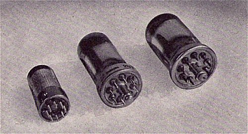
Figure 6.7 From left to right a tube made in A-technique (Rimlock), B-technique (Loctal-8 / B8G), and in C-technique (Key-tube / Loctal-9 / B9G).
Be it as it may, the all-glass envelope was there and it was going to stay. Already in 1938 the use of the all-glass envelope for radio is planned as can be read from Jonkerís Technical Note:
| The development of the all-glass valve has now advanced to such a state that several special valves for television have been introduced, while the introduction next year, of the normal valve series [for radio] in this envelope is seriously being contemplated. In order to gain some experience with the all-glass valve, one receiver type in Holland will be equipped with a single all-glass valve. In order to convince Telefunken of the possibilities of pressed glass, they have fabricated amplifier tubes and rectifiers with a pressed-glass base, underneath which still a normal socket was cemented. It is expected that the all-glass valves will be significant cheaper than the traditional glass valves and metal valves. Additionally, they have better properties for short waves. |
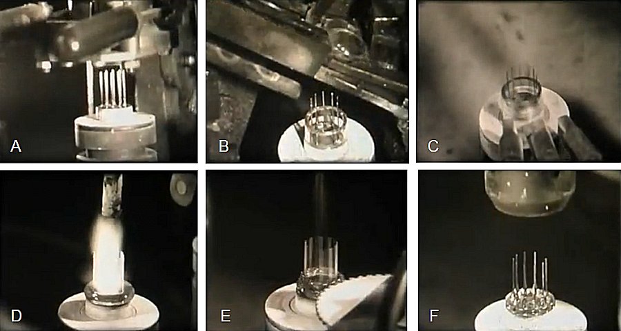
Figure 6.8 Fabrication of a pressed-glass base for Noval tubes. The pictures are stills from the documentary ďthe Blackburn StoryĒ which shows in great detail the fabrication of an EF80 including pressed-glass base. The fabrication of the pressed-glass base is shown in part 4.
A vital part of the all-glass envelope was the pressed-glass base. It is surprising how little information is still around on the actual fabrication technology of this crucial component. Very illustrative however is a movie which was made in the fifties or sixties at Philips-Mullard showing the fabrication of radio tubes. The movie shows in detail the fabrication of a Noval tube and takes the EF80 as an example. The movie also shows how the pressed glass base for Noval tubes was made. It seems reasonable to assume that the fabrication of the pressed-glass base for the C-technique tubes was quite similar.
To start with the nine pins are placed in a heat resistant template (Fig. 6.8 A). In the case of the C and B-technique valves, these pins were made out of the famous Chromium-Iron alloy. After the pins are placed in the template, a simple glass ring is placed around them (Fig. 6.8 B). The glass ring is intensely heated (Fig. 6.8 C,D). When the glass has sufficiently softened a toothed wheel presses the molted glass in between the pins (Fig. 6.8 E). Finally, a mold is pressed over the pins and the molded glass to press the glass into a disk which seals the pins (Fig. 6.8 F).
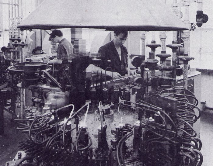
Figure 6.9 A machine for the fully automated fabrication of pressed-glass bases for Noval tubes. Machines like this could spit out up to 2500 tube bases per hours.
Obviously, most of the development work was done at the tube lab in the building on the Emmasingel. However, Klaas Rodenhuis, who was responsible for the professional tube development, clearly remembers how he used to visit the glass factory near the ďGlaspoortĒ (Fig. 6.2 right) in conjunction with the development of pressed-glass (Noval) bases with gold pated pins. So very likely a large part of the development work was carried out at that location.
| to top of page | back to homepage |
Pye Electronics is not that well known outside of Great Britain. Nevertheless, Pye pioneered television in the UK, in 1966 it was the worldís leading exported of mobile radio phones, Pye led the way in instrument landing systems for airports, and it produced Britainís first transistor radio. It was C.O. Stanley, the unconventional Irishman, who acquired Pye Radio at
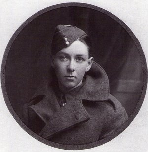 the beginning of the broadcasting age and without much experience or money, turned it into Britainís most important electronics manufacturer, and an international enterprise employing 30.000 workers in Britain and abroad.
Charles Orr (C.O.) Stanley was born the 24th of April 1899 in the little town of Cappoquin near the Southern edge of Ireland [30]. The Stanleys had settled in Ireland some time during the English colonization. They were Protestants, members of the Church of Ireland, and thus marked out from the Catholic neighbours, who stood most to gain from the growing tide of national feeling that swept Ireland. Charlieís father, John Stanley, owned the general store in Cappoquin. John was an energetic man, who like his father did his best to better himself, which was a Stanley family tradition. Measured against the poverties of the Irish countryside at that time, the Stanleys lived a decent, if modest life. At some point in time people started calling Charlie C.O. His sister said it was because he was the Commanding Officer, the one who was always organized and gave orders. The hope that Irish nationalists might abandon their struggle for independence vanished with the Easter Risings of 1916, and the violent events it set in motion. The war of independence that began in 1919 was the final blow to the Stanleyís chance for an ordinary life in Ireland. The protestant Stanleyís were under threat in their hometown of Cappoquin and one by one the children left Ireland to take up positions in London. When they were well established, their parents followed. Charley taught mathematics for a short time at a London school, but in October 1918, just one month before the signing of the armistice that brought the First World War to an end, Charley joined the newly created Royal Air Force.
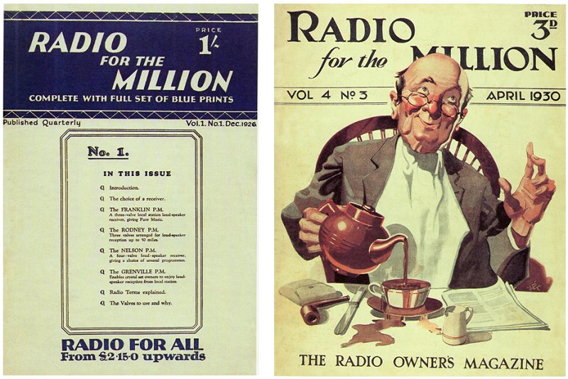
Figure 7.1 Frontcovers of two issues of ďRadio for the Million.Ē The right cover, which shows a man who is so enchanted by the music from his radio that he spills his coffee, was designed by Philip Zec.
When Charlie returned from the Air Force, he again worked for a short time as a teacher. Then, to everybodyís surprise he quitted his job, and told his astonished family that he had applied for a job in advertising with Engineering Publicity Services (EPS) Ltd, and actually got it. EPS most interesting clients were in radio, the new glamorous technology that had caught Charlieís imagination. One of the most valuable clients of EPS was the Mullard Valve Company. The 23 year old Charlie felt so at home in the advertising world that within a year he asked his boss to raise his salary. The latter refused, and when some time later he came across Charlie with his feet on his desk and smoking a cigar a client had given him, he fired him on the spot. Charlie gave no sign that he was upset, on the contrary, after a walk with his brother and sister a simply told them that was going to start his own advertising company, at the age of 24 with less than 20 pounds on the bank, and no more than a few months experience. As Mark Frankland in his book ďRadio ManĒ wrote: ďit was the end of Charley Stanley and the beginning of C.O., the man whose ability commanded the respect of those who grew up him with quite as much as those who worked for him.Ē Together with two colleagues he lured away from EPS, he started Arks Publicity. The company quickly picked up a few small clients, but the breakthrough came when the great Captain Mullard telephoned to ask for a meeting.
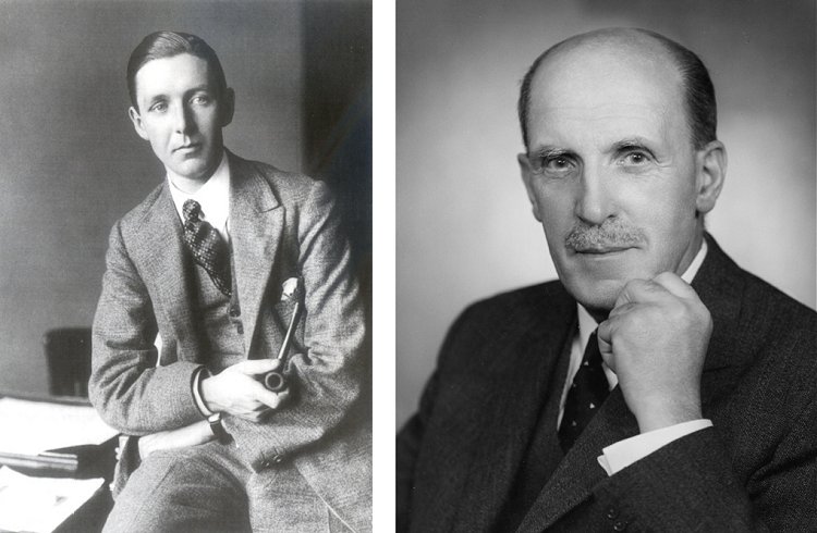
Figure 7.2 Left Photograph, C.O. Stanley c.1929; Right Picture, Captain Mullard ca. 1955 (photo Philips Company Archive).
Stanley Mullard was a famous rough diamond with little formal education, but his experience in the prewar radio valve industry led the British Navy to appoint him to head of his valve-testing laboratory in Portsmouth with
the rank of Captain. After the end of the War, in 1919, he joined the Z Electric Lamp Co. at Southfields, where he soon became managing director.
He mainly manufactured high power silica transmitting valves for the Military and Post-offices. After leaving the Z Company, which subsequently collapsed, he
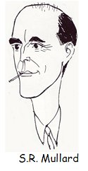 established the Mullard Radio Valve Co. Ltd. in 1920, first in the Z factory and later at Hammersmith. The company moved to larger premises in Balham, in 1922. Besides transmitting valves a small amount of hand built 'R', Weco dull-emitter (thoriated tungsten) and other receiving valves were produced. The same year the Mullard Company was one of the founders of the British Broadcasting Company Ltd. and public broadcasting began in the U.K. The regular radio transmissions increased demand for valves for domestic receivers, and by 1924 Capt. Mullard needed to expand production. He financed this by selling half the shares in the Mullard Radio Valve Co. Ltd. to N.V. Philips Gloeilampenfabrieken of Eindhoven, Holland. In the early days of Radio, most customers built their own radio sets from separate components which often gave problems. C.O. Stanleyís biggest breakthrough with Mullard came when he organized an innovative campaign in which a new magazine ďRadio for the MillionĒ was launched, containing circuit diagrams and building instructions for receivers using Mullardís valves. The whole plan resembled what in Holland AMROH was setting up at about the same time. The campaign was an enormous success and it earned him the picky heart of Captain Mullard. Captain Mullard and C.O. who had a natural liking for each other, set off for a long lasting working relation. C.O. offered what Captain Mullard liked: first-class service, personal trust without bureaucracy and sharp pricing. Not long after the start of the campaign Philips took full ownership of Mullard. Although the unconventional C.O. Stanley clashed with the bureaucratic Philips organization once or twice, Captain Mullard was able to persuade Philips to hire C.O. to give ďadvice and assistance in increasing the turnover in the British Empire.Ē However, C.O.ís future was about to take a turn when in 1928 Captain Mullard introduced him to Pye.
In 1896, William George Pye left his employment as workshop superintendent at the Cavendish Laboratory in Cambridge to set up W.G. Pye and Compagny to design and manufacture high precision scientific instruments [30,31,33]. William Pye was a trained instrument maker, and his equipment for schools physics lessons was in great demand all over the world. The company benefited enormously from the demand for military equipment during World-War I which allowed him to expand rapidly. However, in 1921 this market had disappeared, and the company started to search for something else to manufacture. Partly at the suggestion of Pyeís son Harold, the firm entered the new world of radio manufacturing. At St. Johnís College, Harold had been supervised by Edward Appleton, the same Appleton who several years later would supervise Taffy Bowen, and he who helped Harold to design a new and improved range of receivers, the ď700 SeriesĒ which was quite successful. Ark did some advertisement work for Pye, but Stanley was also interested in Pye in his role as scout for Philips who wanted to expand in Britain. In 1928 C.O. Stanley offered Pye Radio to Philips for £65.000 including a commission of £5000 for himself. Philips refused the offer on the grounds that they did not see any reason to pay Stanley commission for something he was already hired to do! Again Stanley made an unexpected move. With little more than £800 on the bank, he himself bought Pye. He financed the whole transaction by launching Pye radio as a public company, but he was clever enough to place maneuver himself into the position of the majority shareholder.
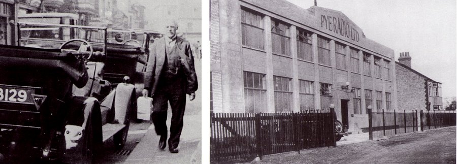
Figure 7.3 Left, W.G. Pye ca. 1932. Right, Pye radio Ltd Cambridge.
Radio was developing at a fast pace. Mains-powered receivers eliminated the need for expensive batteries and ďsuper-hetĒ technology made
receivers much more sensitive. Radio would change the world and Stanley certainly knew where the industry was going. It was less clear what he meant to do with the company he had just bought. Certainly, at first he showed no sign that he wanted to be directly involved in the business of
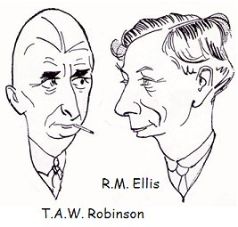 making radio. Later he told friends that he never meant to run Pye himself, but that he planned to sell it on to Philips after launching it as a public company. All this changed when in 1934 sales collapsed. Stanley stepped in, and started re-organizing Pyeís sales organization. It has been suggested that Stanley took this hasty step to have something to concentrate on in the middle of a passionate love affair with Velma Price. His increasing involvement with Pye inevitable meant the end for his co-directors. The truth was that C.O. Stanley could not tolerate equals. Also within a few months of setting up Arks, he demanded and got the consent of his two more experienced partners that he should take charge of the business. At Pye, first R. Milward Ellis, director for sales was more or less forced to leave after C.O. had stepped in to reorganize the sales organization which had been Ellis responsibility.
Next T.A.W. Robinson had to go. Robinson, together with William Pyeís son Harold, had set up to the radio business of Pye. The tireless Robinson was always running through the factory implementing new ideas. Workers joked that he had three brains because of the number of ideas he produced, and they called him ďtear-arseĒ for the way he rushed through the factory [30]. It was mainly Robinson who, perhaps through his training as instrument maker, was responsible for Pyeís high quality of production.
After a conflict over their management responsibilities, T.A.W. Robinson, had no other option then to offer his resignation after he first had accused Stanley of ďun-transparantĒ financial manipulations, an accusation in which he was undoubtedly absolutely right. After Robinsons departure, C.O. Stanley appointed the board he wanted, and from that time on the minutes of the board meetings contained no more criticism of C.O.ís methods.
making radio. Later he told friends that he never meant to run Pye himself, but that he planned to sell it on to Philips after launching it as a public company. All this changed when in 1934 sales collapsed. Stanley stepped in, and started re-organizing Pyeís sales organization. It has been suggested that Stanley took this hasty step to have something to concentrate on in the middle of a passionate love affair with Velma Price. His increasing involvement with Pye inevitable meant the end for his co-directors. The truth was that C.O. Stanley could not tolerate equals. Also within a few months of setting up Arks, he demanded and got the consent of his two more experienced partners that he should take charge of the business. At Pye, first R. Milward Ellis, director for sales was more or less forced to leave after C.O. had stepped in to reorganize the sales organization which had been Ellis responsibility.
Next T.A.W. Robinson had to go. Robinson, together with William Pyeís son Harold, had set up to the radio business of Pye. The tireless Robinson was always running through the factory implementing new ideas. Workers joked that he had three brains because of the number of ideas he produced, and they called him ďtear-arseĒ for the way he rushed through the factory [30]. It was mainly Robinson who, perhaps through his training as instrument maker, was responsible for Pyeís high quality of production.
After a conflict over their management responsibilities, T.A.W. Robinson, had no other option then to offer his resignation after he first had accused Stanley of ďun-transparantĒ financial manipulations, an accusation in which he was undoubtedly absolutely right. After Robinsons departure, C.O. Stanley appointed the board he wanted, and from that time on the minutes of the board meetings contained no more criticism of C.O.ís methods.
| to top of page | back to homepage |
With the invention of television, or ďTelevisorĒ as he called it, by the Scotchman John Logie Baird in 1922, Britain was destined to play a leading role in the development of this new medium [32]. Bairdís system was mechanical, and the bandwidth of the video signal was low enough to allow transmission via a radio channel. Despite its many imperfections and poor image quality, Baird tirelessly promoted and demonstrated his system and finally in 1930 went into production. At about the same time EMI (Electric and Music Industries) developed a more promising television system based on cathode ray tubes and an electronic scanning camera. The BBC started with very limited broadcasts with the Baird system in 1932. In 1936, they began the worldís first regular television broadcasts of just 2 hours a day from Alexandra Palace in London. During a trial period, these transmissions alternated between the EMI and Baird systems, and sets had to be able to receive both. Finally, in 1937 the BBC decided for EMIís superior 405 lines system.
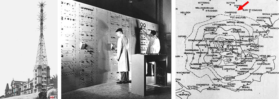
Figure 8.1 Left, the Alexandra Palace transmitter. Middle, the EMI-Baird control room. Right, the coverage range of the Alexandra Palace transmitter. Cambridge (red arrow) is indeed on the edge of this range.
From as early as 1925, Pye had taken a keen interest in television. Early 1935, Pye set up a small subsidiary called Cathodeon to carry out research into cathode ray tubes (CRT) [30]. Early-1930s CRTs were still an obscure research instrument for observing waveforms. It is hard to imagine now, but it required a considerable research effort to solve problems of Phosphor color, efficiency and reliability, electrical focusing and deflection, in order to make the CRT suitable for television. Later L.F. Broadway of EMI recalled ĎÖ at that time we believed that the CRT as a display device was only an interim measure. We didnít really believe that this huge vacuum envelope, a cumbersome sort of thing, would last [31].Ē In 1932 Peter Goldmark set up a television department at Pye, but was forced to leave 18 months later when he was told that ďtelevision probably would never be useful for the home.Ē A year later however, Pye had to restart their television development because they recognized that it was effecting their radio sales.
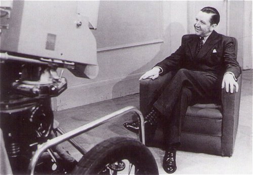
Figure 8.2 C.O. Stanley in his capacity as chairman of the Television Development Committee of the Radio Manufacturerís Association, being interviewed on television about their plans for Radiolympia 1938.
After having reorganized the sales organization, C.O. television became C.O. Stanleyís new pet project. This was exactly the thing he was good at, to market a new technology, to champion the mission of radio and television to entertain, and to attack monopoly control over broadcasting by the government, the BBC or any other establishment of the great and powerful. C.O. like no other understood that the sales of television would heavily depend on the availability of popular content, and that was not what the BBC was providing. Throughout the thirties British radio listeners preferred Radio Luxembourg over the BBC. Within no time C.O. managed to become the chairman of the Television Development Sub-Committee of the Radio Manufacturers Association which wrote critical reports on BBC television programs.
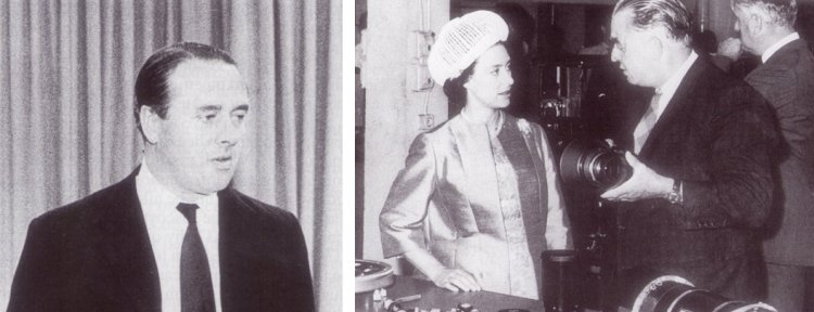
Figure 8.3 Left, B.J. Edwards 1958. Right, Princess Margaret and Donald Jackson 1963.
To lead the television development team, Pye recruited Baden John Edwards and Donald Jackson who were at that time both engineers with Standard Telephone and Cables, the British daughter of the American ITT. Stanley persuaded them by sharing with them his dream about television, and Pyeís and their role in it. Edwards has been described as a maniac [34]. He was temperamental, over-bearing and often foul-mouthed. Donald Jackson was eccentric to such an extend that he became known as ďmad Jackson.Ē To the surprise of his wife he once removed all the internal doors in his house so that he could move around more quickly.
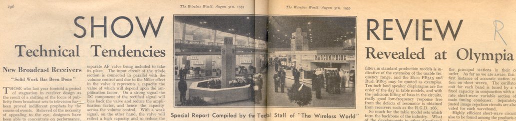
Figure 8.4 Header of a review article in ďThe Wireless WorldĒ discussing the novelties at the 1939 Radio show in the Olympia Hall [35]. Click here to view the original article.
Through a combination of cheaper television sets, and more attractive television programs sales of televisions increased, and in 1939 in total 19000 sets had been sold, more than every country including the USA. Pyeís research efforts paid of, and in 1939 they were the third largest television maker after EMI and Ekco. In 1939 Pye was preparing to show their latest and best design, the 915 model, on the annual Radio show. So far the reception range of the Alexandra Palace transmitter had been limited to about 25 miles. With the 915 model, Pye wanted to increase this range to include Cambridge (50 miles). To achieve this, B.J. Edwards had to design a receiver with an until then unheard of sensitivity. The receiver architecture that Edwards and Jackson had chosen was that of a Tuned Radio Frequency (TRF) design, also known as a ďStraight ReceiverĒ. Since there was only one station transmitting television signals, there was no need for the receiver to be tuned, so why bother with the complexity of a ďsuper-het?Ē Also within Philips the TRF receiver was being evaluated for television. In a Research Technical Note van der Ziel discussed the possible TRF architectures for television. For his TRF receiver Edwards needed an RF amplifier tube with excellent high frequency properties.
Now at this point, most publications on the history of the EF50 suggest the following sequence of events: Edwards and Jackson ďinvented,Ē or at least put down the specifications for this new tube and commissioned Cathodeon or Hi-Vac, - another Pye subsidiary - to make it. They failed to produce this tube, at least in sufficiently large quantities, so they discussed the problem with Mullard. Mullard subsequently tailor made the
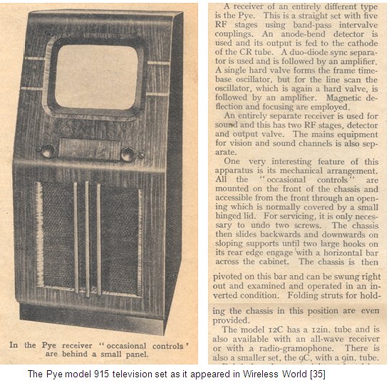 tube according to Edwards specifications and it became known as EF50. Then most publications suggest that Mullard was not able to manufacture then in quantity, so that it was Philips in Eindhoven who took up Edwards design and mass-produced it, with the tubes stamped with Mullardís name.
The first thing to explain here, is that the EF50 does not really constitute an invention in the classical sense of the word. The electrode system in the tube itself is rather conventional, and certainly contains no breakthrough innovations; it is the all-glass envelop with its short lead-in wires which to a large extend resulted in the improvement in performance. All tube manufacturers had about that time realized the limitations of radio tubes made on a pinch. Especially the high parasitic capacitances and inductances in the lead wires severely reduced the gain at high frequencies. A number of companies had, as we have seen, introduced tube envelops with reduced parasitics, such as the different types of metal tubes or the ďStahlrŲhreĒ from Telefunken. But these tubes also had their drawbacks, they were without exception expensive to manufacture, and they were difficult to scale down in size. The all-glass concept was therefore ďsomething that was hanging in the air.Ē The RCA Acorn tube was of course a clear example of an early all-glass tube, but also Sylvana arrived at the all-glass envelop at almost exactly the same time as Philips. If it is one thing that Philips added, it was that they took up the concept and developed it into a low-cost product suitable for automated, high-volume production. Something they were very good at.
The second point to add is that the development of the all-glass valve at Philips had already started as early as 1934 when RCA introduced their Acorn tube. Indeed in his letter to the board of directors, Sluiters complained that the development of the all-glass tube took more than 5 years (from 1934 to 1939). The development of the all-glass valve was therefore part of the natural evolution of the vacuum tube, and was certainly not ďinventedĒ or designed by Pye. Most publications by Philips on Television circuits at that time are based on the EE50 tube, a secondary emission tube combining a high mutual conductance with a low input capacitance. Consequently, some authors conclude that Philips had developed and used the EE50 [36] for its own television receivers, so that the EF50 must have been developed exclusively for Pye [31, p255]. However, the publications discussing the application of the EE50 for television are almost all research papers, and they do not necessarily reflect the opinion of the (tube) development groups or the groups involved in the design of television sets. Secondary emission tubes were a pet project of Hans Jonker, who headed the tube research group. Secondary emission tubes, however, had some serious manufacturing and reliability issues. Knowing Philips they would never bet their money on one horse, and certainly would always make sure that next to the more advanced research tube, they also would have a proven concept tube to fall back on if needed, the EF50. This does not mean that Pye didnít have any part in the development of this tube. Jackson at least on one occasion visited the engineers in Eindhoven to discuss technical problems and specifications [34]. It seems very likely that these discussions with, as Tromp put it ďan important customer,Ē have contributed to the final realization of the EF50.
In the mean time Edwards and Jackson were working hard to get their model 915 receiver ready for the August Radio show. Apparently the TRF receiver with the five EF50 tubes was the most difficult and critical part. Mark Frankland in his book Radio Man writes:
| ... it [the EF50] failed to perform to Edwards specifications. With the August Radio Show approaching Stanley told him [Edwards] to call the best electronic engineers at the university to help solve the problem, but Edwards and Jackson, working with the Mullard team, came up with a mechanical solution of their own. First they improved the valveís performance by altering its base, only to get more distortion because of poor screening of the valveís inner surface. With not time to send the valves back to Eindhoven to be rescreened, Jackson devised the ďJackson cap,Ē a small red spun-metal jacket placed on top of the valve. Arranged after hours of experimenting in an unusual requence of five, it was largely the EF50 that allowed Jackson to call the 915 set ďthe greatest [television] receiver in the world.Ē |
The final reason brings us back to the original line of this story, Radar and the role the EF50 would play in it. At the same time that Edwards and Jackson were designing the next generation television set at Pye, some 100 km to the East in Bawdsey, Bowen and his team were working hard to get the airborn Radar system in working order. He had demonstrated the principle, but incredibly enough still had only one 45 MHz receiver that could meet the stringent specifications for the Radar system. Then by a stroke of good luck, in April or May of 1939, Bowen is tipped by his former professor Edward Appleton that Pye at Cambridge had developed a sensitive 45 MHz TRF receiver. Bowen immediately went to Cambridge to find that Pye had ďscores of TRF chassis of the type that they were looking for [9].Ē So obviously the development of the chassis had taken place quite some time before this visit!
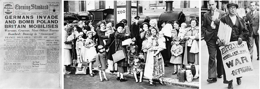
Figure 8.5 The First three days of the war in Britain. On the 1st of September the Germans invade Poland. The following day Woman and children are evacuated at Victoria Station. On Sunday the 3rd of September France and Britain declared war on Germany.
The Radio Show in the Olympia Hall opened the 23rd of August. The model 915 television set from Pye was well received at the Radiolymia with a photograph and a favorable review in Wireless World [35]. The review specifically mentioned that it is a ďstraight set with five RF stages using band-pass intervalve couplings.Ē The combination of probably one of the best RF valves at that time, with the brilliant circuit designed by Edwards and Jackson, made it probably the best receiver in the country. However, grave events in the world made that the receiver would fulfill a completely different task then for what it was designed for. On Friday the 1st of September, one day before the official end of the Radio Show, Germany invaded Poland. Despite an Anglo-French ultimatum, Germany continued its blitzkrieg in Poland, and on Sunday the 3rd of September, Britain and France declared war on Germany. These dramatic events completely upset the normal day routine of the entire British Nation. It also ment a premature end of the Radio Show which was closed on Friday and a postponement of all television broadcasts for the duration of the war.
| to top of page | back to homepage |
In the story of Radar, Professor Edward Appleton sits like a spider in its web. In 1920 he was appointed ďassistant demonstratorĒ in experimental physics at the Cavendish Laboratory [3]. He specialized in atmospheric physics, mainly using radio techniques. In 1921 he helped Harold Pye, whom he supervised as a student, to design a new series of radio receivers when Pye diverted its business to radio receivers. It is therefore only natural to assume that he kept some kind of special relation, or at least special interest in Pye. Probably, in this way he became aware of the special highly sensitive 45 MHz receiver Edwards and Jackson had realized using the EF50. In 1924 Appleton was appointed Professor of Physics at London University. There he supervised Taffy Bowen during his PhD. Appleton must have been a welcome guest in government circles, because as soon as the war broke out, he was appointed to a function which basically amounted to scientific advisor of the government. In this function, he undoubtedly must have known of the development of the Radar system Bowen was working on. In this way it is therefore highly plausible that Appleton was the one of the few people that Bowen could turn to, to discuss technical problems and issues.
One of the problems Bowen was facing was that while early 1939 all components of the Airborn Radar seemed to have fallen in place, he still had only one receiver which up to that moment no supplier had been able to duplicate. But then quite unexpected his old professor comes up with a golden tip:
| Quite by chance in april or May of 1939, I heard some encouraging news from Edward Appleton, my old professor at Kingís Colledge and now Jacksonian Professor of Physics at Cambridge. He told me that the Pye Radio Compagny, still hoping that there would be a television industry in Britain, had set up a production line for 45 Mc/s TRF chassis and had actually made a trial run. I went hot-foot to Cambridge to see B.J. Edwards, the Technical Director of Pye Radio, and was rewarded with a remarkable sight Ė he had scores [!] of TRF chassis just the type we were looking for. These used a new valve with an octal [sic] base, which had not yet appeared on the market. It was the EF50, a valve which was destined to play almost as important a part in Radar war as the magnetron itself (Click here to view full text) [9]. |
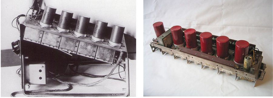
Figure 9.1 Left, part of an original model 915 chassis. Right, A Pye strip used in early Radar receivers (Photograph Pye Telecom History Group).
For Pye, and C.O. Stanley in particular, this came as a gift from heaven. Early 1939 preparations for war were in full progress, and so far there had been hardly a role in it for Pye and its Irish director. This was obviously nothing for C.O. who, as Dennis Fuller put it, Ďwas maddened not to be in the tick of it.í C.O. had even gone as far as to ask friends how he could get a war-related job in Whitehall. With the discovery of the EF50 TRF strip by Bowen this all changed and from one moment to the other, both Pye and its outspoken director were up to their ears involved.
By the end of July 1939 the complete airborne Radar system had been installed in the Blenheim. Bowen was relieved to see that it functioned as expected and was anticipating an order for a few more prototypes. What happened next came as a shock to the whole Radar team. At the beginning of August the Air Ministry placed an order for no less than 30 transmitters and power-supplies with Metro-Vickers and the same number of receivers with Pye. This equipment not only had to be manufactured, but also fitted to 30 squadron aircraft in 30 days, literally by the 1st of September! Fortunately, Bowen managed to persuade the Air Ministry to include in the Pye contract most of the switching-gear, power supplies, control panels and the rest of the components which make a complete assembly, but many of the small bits and things were nevertheless still missing [9]. Bowen had a team of only 23 people, and the completion of the order for 30 Radar systems could only be completed with the help of Pyeís television engineers who, at the same time that in London the Radiolymia was in full progress, overnight became Radar experts. By what Bowen called ďprodigious efforts,Ē six Radar equipped Blenheims were delivered to the 25th squadron by the end of the month, and on the first night of the war there was literally only just one Radar equipped Blenheim night-fighter to patrol the sky over London [30]. The way the Pye engineers instantly dropped everything to realize the often absurd requirements of the Air Ministry was characteristic for the way Pye operated during the war. It was exactly this flexibility which made them a preferred supplier with the War Ministries [34]. An essential part of Pyeís job, according to Anita Sturrock, one of Pyeís researchers, was ďturning pie-in-the-sky ideasí into something practicable [30].
In the course of the period 1939-1940 a whole set of supplementary Radar systems was installed all over Britain to fill up coverage gaps in the original Chain Home system. Most of these systems used the 200 MHz carrier frequency that was also used by Bowen in his airborne Radar. One after the other the engineers and scientists who worked on these systems discovered the Pye strip powered by the EF50, often completely independent of each other since the secrecy surrounding the Radar program was so strict that development groups were often not informed over each otherís activities. With the number of Radar systems growing also the demand for EF50 tubes increased.
Up to that moment nobody seemed to have worried about the supply of EF50s. C.O. had a large stock of them in a warehouse at Newmarket [30].
The tubes were naturally supplied by Mullard, and everybody must have assumed that Mullard was well capable of producing this new tube. Bowen writes: ďwe were told that the EF50 was manufactured by Mullard, and we were assured that it was in good supply.Ē In reality, large-scale production of the new glass envelope presented major difficulties so that most of the EF50 tubes that Mullard supplied to Pye came directly from Eindhoven [20]. Especially the production of the disc-like glass base was difficult since it required new machines and special glass. Mainly using imported bases from Holland, there was some pilot production under supervision of F.A. Kloppert, the head of the Mullard valve factory in Mitcham, and Dr. O.S. Pratt, head of Mullard development and quality lab. When the war broke out in Britain, efforts were increased to establish full large-scale production in order to make the plants in Mitcham and Blackburn independent of Eindhoven [20].
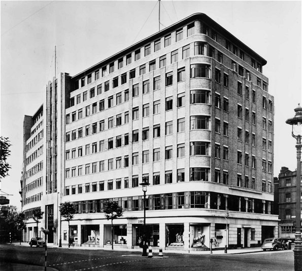
Figure 9.2 Century House, Shaftsburry Avenue London where the head office of Mullard was located. Here in S.S. Eriks office, Tromp met Watson-Watt (Photo Philips Company Archive).
C.O. Stanley was the first to see that operational Radar sets would need many more valves than his store-rooms held. Although the exact chain of events has not been recorded, Mullard at one point must have admitted that they had difficulties in producing the EF50. Shocked, the principal people involved realized that for the production of one of the key components of their precious Radar systems, they depended on tubes imported from Holland, which was itself under threat of invasion by Germany! C.O. himself turned to Philips and learned that there was a considerable stock of EF50s in Eindhoven. When he learned this, C.O., according to Fuller ďturned into a demon.Ē He was desperate to convince the government that they must send a ship to collect the entire stocks of EF50 as soon as possible. They wouldnít listen, or if they did they didnít seem able to find a ship, but C.O. wouldnít stop. He rung and pestered everybody he could think of and then started sending people in the ministries letters and telegrams. He finally told some general that if they didnít collect the valves immediately, he personally would send two lorries to Harwich, hire a boat and go and collect the valves himself!Ē
It didnít come to that, somebody in the ministry, very likely Watson-Watt himself, must have grasped the severity of the situation, for the next thing we know is that Theo Tromp was instructed in February or March of 1940 to go to England. Theodoor Philibert (Theo) Tromp was at that moment the head of all tube development and manufacturing in Philips, as well as of the Radio Valve Foreign Department. He was in the Philips organization an important man, not just somebody who could be instructed by anybody to go somewhere. Besides this, Britain was at that moment already half a year at war with Germany, and it was for people coming from Holland very difficult to get into England. The fact that Tromp specifically writes: ďI was instructed to go to England,Ē therefore implies that this order came from somewhere very high in the organization. It seems likely that either the British government contacted Anton Philips directly, or that they made a request for contact with a senior manager responsible for tube manufacturing at Philips through the Dutch government. Anyhow, as soon as the official documents had been arranged, Tromp travels to London.
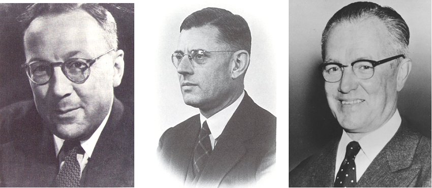
Figure 9.3 From left to right: Robert Watson-Watt, Theodoor Philibert Tromp (Click here for a biography), S.S. Eriks managing director of Mullard Valves (photo Philips Company Archive).
On a Saturday afternoon, after closing hours, Tromp had a meeting with Watson-Watt in the office of S.S. Eriks, the managing director of Mullard in Britain in Century House in Shaftsbury Avenue, London. During that meeting Tromp hands over to Watson-Watt a special infrared tube that was developed by Philips Research and that could be used by the British to look over the channel at Dover to the German gun emplacements at Calais from where they bombarded England with heavy guns. The tube was later produced by GEC and used exactly for this purpose. At the same meeting Watson-Watt informed Tromp that:
| ... that the British Government was most anxious to set-up a large scale production of EF-50 (and also EL50) in England and requested me, if possible, to supply Mullard with all the production equipment and special tools for these valves, together with a very large number of complete sets of components for the EF50. This to enable Mullard to start production of the EF50 in quantity already before they would be able to make their own components in large quantities for full-scale production at Mullardís (Click here to read Trompís letter to Mr. Bell [20]). |
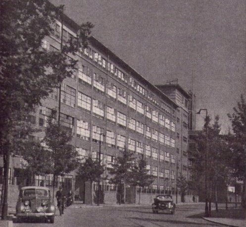
Figure 9.4 ďThe White Lady,Ē the nick name of the enormous complex at the Emmasingel in Eindhoven where the tube development groups (4th floor) and tube fabrication plants were located. It was here that the EF50 found its origin.
The technicians and tool shops at the Emmasingel work day and night to comply with Trompís request, and finally in the evening of the 9th of May a truck was loaded with the machines which had been hurriedly put together, and no less than 25,000 complete EF50s and 250,000 tube bases. It was for everybody clear that the Germans could invade Holland any moment, but nobody loading that truck that evening could have guessed that hours later, around five oíclock the next morning, the Germans would actually cross the border with Holland. Having no idea of the events that lay ahead, the driver headed to Vlissingen where the precious cargo would be transported to Britain by one of the ships of ďZeelandĒ steamer company (ZSM). After the war in England had officially started the 1st of September 1939, service to Harwich had become difficult. From the 25th of November service was suspended altogether, and all ships were grounded. The shipment of the machines and components therefore must have been carefully planned. Most likely Tromp himself played an important role here. Besides his job with Philips, Tromp also happened to be a government commissioner (ďregerings commissarisĒ) with the ZSM.
By the time the Germans crossed the border, the machines and components in all probability had already been loaded into one of the ships, and when news reached the coast of the events at the Dutch-German border, all three ships of the ZSM were hurriedly prepared to leave for England. On sea, all three ships were attacked by German airplane bombers and the ďPrinces JulianaĒ was damaged so badly that it had to return to Hoek van Holland. The brand new sister ships ďKoningin EmmaĒ and ďPrinces BeatrixĒ were also attacked, but safely reached Downs. Which one of these two ships carried the tubes is unfortunately unknown. The ships reached London the 15th of May 1940, where they were converted for military service. The head office of the ZSM in Vlissingen was damaged so badly during German attacks that after the war the service was resumed from Hoek van Holland.
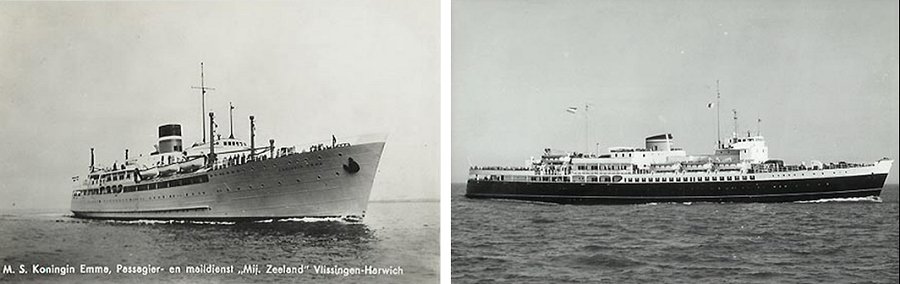
Figure 9.5 The diesel sister ďKoningin EmmaĒ (left) and ďPrinces BeatrixĒ (right). One of these ships carried the EF50s and the machines to make them to England the 10th of May 1940.
Philips had prepared itself very thoroughly for the impending war. It had taken a whole series of elaborate measures to protect their goods and production facilities all over the world should Holland be invaded [39]. A detailed evacuation plan was put into working the moment the news reached the Philips top that the war had started. Vital machines and equipment were loaded onto trucks and a long row of trucks and cars left Eindhoven the first day of the war. Only a fraction of this motorcade managed to reach the coast. The largest part got stuck at the bridges over the large rivers which were in the hands of Germans paratroopers, and eventually they returned to Eindhoven. Most members of the Philips family including Anton Philips and almost the complete board of directors (Otten, Loupart and Van Walsem and families) reached Den Haag (The Hague). In the evening of the 13th of May they were evacuated together with the Dutch government from Hoek van Holland by the British Destroyer H.M.S. Windsor after the Royal Family had been evacuated earlier that day by the H.M.S. Hereward. The next day Rotterdam was literally flattened by German bombers after which Holland capitulated.
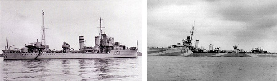
Figure 9.6 Left the H.M.S. Hereward which evacuated the Dutch Royal family from Hoek van Holland, Right, The H.M.S. Windsor which at 19:20 in the evening of the 13th of May evacuated the Dutch Government, The Philips Family and most of the board of directors of Philips.
Just before the Philips family was evacuated to Britain, a small wooden box was delivered to Anton Philips under very difficult circumstances. The box contained industrial diamonds, and they were destined for the Mullard plant in Blackburn, to be used for wire-drawing dies. It was the last thing the mother company in Eindhoven had been able to do for their daughter Mullard; from now one they would be on their own. War or no war, when the diamonds arrived at Dover with the Philips family, they were impounded for some days, until a Board of Trade Official and an expert summoned from Blackburn had worked out the duty on them and a bankerís draft for the amount had been duly received [31].
| to top of page | back to homepage |
We should not forget that already before the EF50 there were other tubes available that also did a pretty good job. Keith Geddes in “The Setmakers” writes: ‘The ubiquity of the Philips-designed EF50 valve both during and after the war, and the dramatic circumstances attending its production tend to obscure the importance of the slightly earlier valve designed and made by Mazda, which was likewise introduced for 45 MHz amplification in television sets. The SP41, with a 4-volt heater, was given a 6-volt heater for military applications, and as the VR65A made major contribution to the Battle of Britain, through its use in the R1132 VHF ground receiver. VHF radio communication between fighter aircraft and ground stations was vital to the aircraftsí deployment. The valve was also used in early airborne Radar equipment and (under a different number) by the army, and was produced in great quantities at a “shadow factory” in Baldock which in peacetime made silk stockings.[31]’
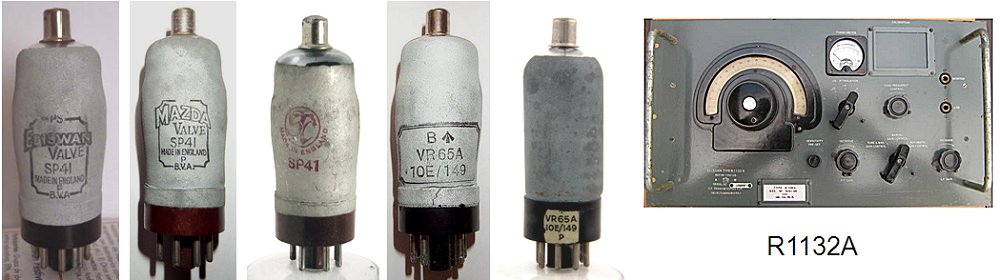
Figure 10.1 The RF workhorses before the EF50, the SP41 with a heater voltage of 4V and the VR65A with a heater voltage of 6.3V. The later was extensively used in RF equipment such as the well known R1132 VHF ground receiver.
The EF50 was quickly type approved by the military, and became knwon by the Air Force as the VR91 and by the army as the ARP35 and CV1091. It replaced the VR65A and in many cases the difficult to produce Acorn tubes in RF and IF amplifiers and in precision time base circuits such as those developed by F.C. Williams of T.R.E. The EF50 was copied and produced in large numbers by amongst others Sylvania in the U.S.A. which had similar developments in all-glass tubes before the war as Philips (see Fig. 6.3) [12].
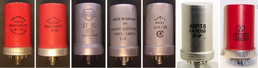
Figure 10.2 A selection of EF50 samples. The Air Force type code was VR91, the Armyís type code ARP35 and CV1091.
The first supplier of the EF50 was of course Mullard. However, the ties of Mullard to Philips in occupied Holland made the British officials cautious, Keith Geddes [31]:
| ... Cut off from Eindhoven, Mullard opened their first Research Laboratory, located at Bournemouth and headed by Bob Clarke, who had run the Technical Department at Mitcham. Sadly but inevitably, the British Governmentís attitude to Philips Lamps Ltd changed. From being a neutral country, it became a company many of whose senior staff had close relatives in enemy-occupied territory, and as such it could no longer be considered totally secure. Thus when the main production of EF50s was transferred to Blackburn, in the latter part of 1940, the Mullard and Philips parts of the complex were kept strickly separate, and commissionaires were posted outside the Mullard factory with instructions to keep all Philips personal out, though after a year or so relations became more relaxed. At Mitcham, Philipsí Plant director was for a time under house arrest, being driven to and from work each day. Mullard also had many Dutch staff, from Eriks downwards, but were excluded from the more secret projects, and a young graduate who joined Mullard at Mitcham in 1941 found that they had not yet gone over entirely to war work. As the war progressed, Blackburn overtook Mitcham both in its output of valves, with figures of 6.5 and 5 million respectively in 1944, and in productivity. The plant drew its own tungsten wire (with diamonds from Eindhoven), made its own metal components and its own glass, and by the end of the war claimed to be the biggest and most “in depth” valve-making unit in the western world. |
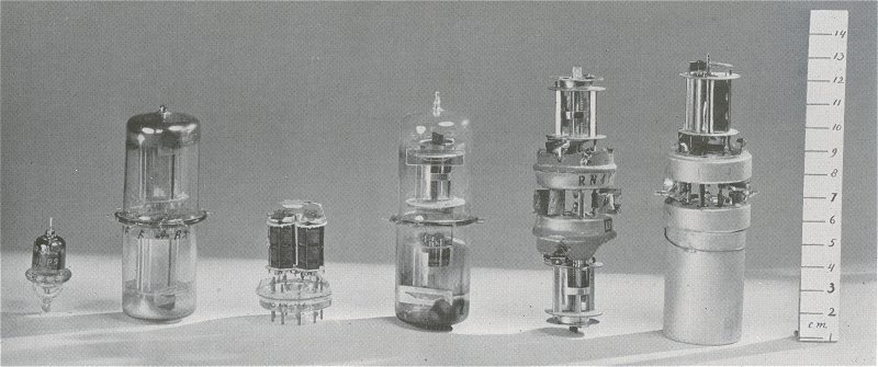
Figure 10.3 Acorn pentode 4672 (left) and a number of developmental models of the push-pull amplifier valve EFF50. The third from the left shows the final model [28].
The theoreticians behind the development of RF tubes at Philips Research were, as we have seen, in the first place Max Strutt and to a lesser extend Aldert van der Ziel. In his paper ‘A new push-pull amplifier valve for decimeter waves’ in the Philips Technical Review of December 1940, Strutt extensive elaborates on the factors which were at that time limiting the improvement in RF performance of short-wave radio tubes [28]. A first observation which may be derived from this publication is how advanced the research into radio tubes was already before the war! For the characterization of radio tubes voltages and impedances could be accurately measured up to 1.5 GHz, a remarkable achievement! Furthermore, the theory on amplification and noise in radio tubes was very well developed. The bottlenecks in the design of even better valves was very well understood. A standard way to improve the high frequency performance of valves had always been to increase the transconductance by decreasing the grid-cathode spacing. In his paper, Strutt demonstrates that the development of RF tubes had now arrived at a point where a further decrease in dimensions did only result in marginally better performance.
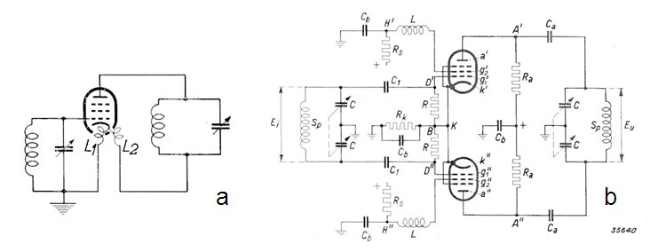
Figure 10.4 Schematic representation of the ďdouble cathode connectionĒ as used in the EF51 (left), and the push-pull amplifier EFF50 (right).
Even using the newly developed all-glass (EF50) envelope, it was not possible to push the performance of the tubes into the 200-300MHz regime.
The cause was again found in parasitic inductances in the cathode lead of the tube. The first method that Strutt and Van der Ziel proposed to combat the remaining cathode inductance was to use a push-pull configuration (Fig. 10.4). In push-pull operation two pentode sections are integrated in one envelope so that they share the same cathode lead. The tubes are used in a balanced configuration in such a way that when in one section the AC anode current increases, it decreases in the other section. The result is a zero current change in the cathode lead and hence zero feedback! The double pentode was christened: EFF50. Figure 10.3 shows the development steps towards the integrated double pentode. Somewhat later the EFF51 was added to the EFF50. It is not exactly clear what the differences are between the two tubes. Despite the publication date of the paper of Strutt (June 1940), the tube was in fact already available towards the end of 1939. In the minutes of a meeting of the commission for the “Coordination of Valve Development” (CVD) in Britain held at Signal School the 16th of January 1940 we read that: ‘W.B. Lewis had tested samples of EFF50, a double tetrode (SIC) supplied by Mullard/Philips, which operated up to 300MHz [12].’ The push-pull construction worked very well, and in practice outperformed the Acorn pentode. In the EFF51 datasheet the tube was advertized as an amplifier usable up to 500MHz.
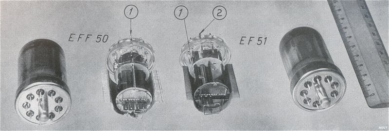
Figure 10.5 The EF51 compared to the EFF50. The numbers indicate the cathode connections [29].
The EFF50/EFF51 fully answered to the expectations. In practice however, it is not always possible or convenient to use this circuit topology. The implementation is much more complicated, the power consumption is doubled, and it is difficult to implement variable amplification. Strutt and Van der Ziel therefore used another trick “the double cathode connection.” In this relatively simple construction the internal cathode is connected to two separate pins. One pin is made part of the input circuit, while the other pin forms a part of the output circuit. In this way the anode current which returns to the cathode no longer needs to follow a path which comprises the input circuit.
Figure 10.5 depicts the practical implementation of the double cathode connection. Special care was taken to reduce especially the inductance of the “input-cathode” by placing the electrode system as close to that pin as possible. The control grid of the EF51, in contrast to the EF50, has an irregular pitch. In this way the magnitude of the negative control voltage which is necessary to suppress the anode current is made different for different parts of the cathode. As a result the “cutting-off” of the anode current for decreasing grid-bias takes place gradually. The result is that the change in slope also takes place quite gradually. Thanks to this property it is possible to regulate the amplification of the valve by changing the grid bias.
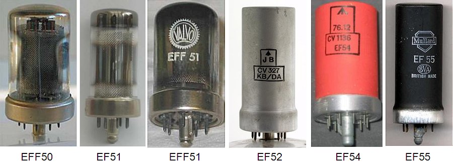
Figure 10.6 The family of EF50 derivates.
In 1940 Mullard produced the RL7. Like the EF51 it also had two cathode connections, but additionally had aligned grids to reduce partition noise. Partition noise is generated by the fraction of anode current interrupted by the second grid. This produces a noise voltage which acts on the anode current, so causing an increase in the noise current carried by the beam. The effect can be minimized by accurate alignment of the ;grids, so that almost all the electrons passing through the first grid reach the anode without being intercepted by the second. The RL7 was type approved as the VR136/CV1136 and surpassed the Acorn tube as a low noise amplifier at frequencies up to 300MHz. The entire 200MHz Radar receiver could now be built with mass-producible low cost components [12]. After the was the VR136 was sold as the EF54.
On the 7th of June, pre-war announcer Jasmine Bligh stepped before the camara and spoke the in the mean time historical words: ‘Good afternoon everybody. How are you? Do you remember me, Jasmine Bligh...’. With these words the BBC resumed their television service from Alexandra Palace. It was still a time when everything was in very short supply, and the only viewers at that moment were the viewers who already owned a television set when the war started six years earlier. What in the end turned out to be the greatest obstacle for the full scale production of new television sets was the shortage of timber for the cabinets [31]. However, by the end of 1946 Pye was one of the first to be on the market with their B16T 9 inch screen table model. The B16T as well as the full scale D16T still had a TRF ďstraightĒ receiver like the pre-war models, but some significant improvements had been made. Wireless World pronounced it ‘very considerable superior to comparable pre-war models.’ Its success largely arose from its strip of RF stages using EF50 valves, which was based on Pyeís 1939 design but also embodied the experience acquired in making such strips as IF amplifiers for Radar receivers. Click here to see a charming demonstration of a D16T.
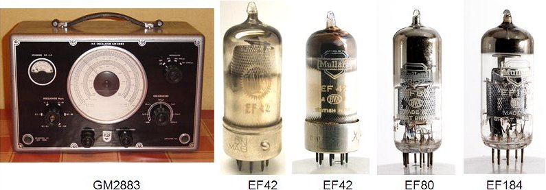
Figure 10.7 After the war the EF50 was used in measurement equipment such a the GM2883 RF generator (left). The pictures on the right show the successors of the EF50: the EF42 (German and British version brotherly next to each other, 1948), the EF80 (1951) and finally the EF184 (1960), both in Noval envelopes.
After the war the EF50 found application in industrial applications and measurement equipment such as the Philips GM2883 RF generator. Starting from 1948 the EF50 was replaced by the EF42 in the Rimlock envelope which was developed during the war. The UF42 is exactly the same tube, but with a filament for 100 mA series supply. The Rimlock series was quickly succeeded by the Noval envelope and from 1951 onward the EF42 was replaced by the “evergreen” EF80. A beautiful movie was made by Mullard showing in detail the fabrication of the EF80 in the Blackburn plant. The EF80 in turn was succeeded in 1960 by the last member in this series, the EF184.
| to top of page | back to homepage |
The South of Holland - the part below the big rivers - was liberated in the autumn of 1944, while it took until the spring of 1945 before also the northern part of Holland was liberated. Eindhoven itself was liberated the 18th of September 1944. Five days later, on the 23rd, Philips Research was visited by a field-party of the Combined Intelligence Objectives Sub-Committee (CIOS), whose task it was to compile dossiers about Nazi and foreign engineers and scientists [45]. The field party was headed by no-body else than Watson-Watt who wrote the summary to the extensive report the committee produced [46]. The committee established that:
| The Germans clearly did not entrust to Philips any secret project or even any element of a project large enough to be discernible as part of a secret. Thus they made substantially no use at all of the exceptionally fine laboratory organisation before mid-1942, and failed to get two percent of its potential usefulness after that date [46]. |
| Auto-sabotage in the German Organization: the German system of allocation and control was, as the Philips management said, the most effective sabotage agency known to them.The proliferation of papers, the failure to devolve responsibilities, the refusal to exercise initiative,the appointment of technical incompetent supervisory and progressing officers, and the concentration of attention on clearing the documents rather than the materials, sufficed in themselves to impede production. Exploited by an expert and ingenious body of non-cooperators,this system lent itself to a double frustration [46]. |
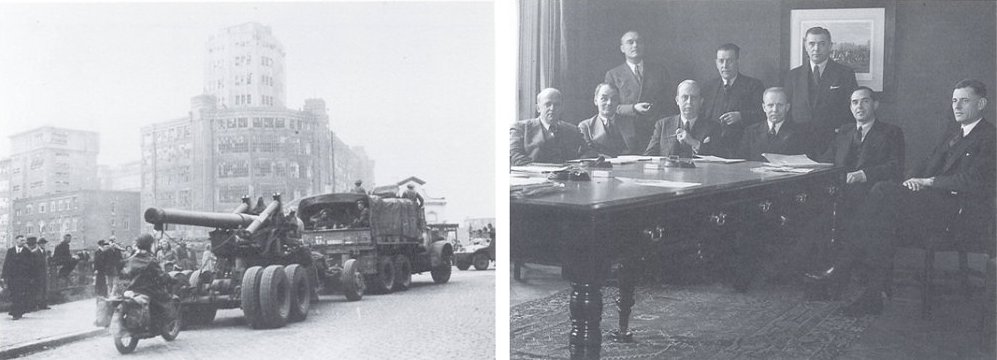
Figure 11.1 Left, the Allied Forces entering Eindhoven. In the background the White-Lady heavily damaged. Right, the board of directors of Philips after the war. From left to right: O.M.E. Loupart, A.J. Guťpin, P. van den Berg, H.F. van Walsem, P.R. Dijksterhuis, P.F.S. Otten (President), J.C. de Vries, F.J. Philips (Vice-President), and Th.P. Tromp.
Already before the war, Anton Philips had transferred the control of Philips to Frans Otten, his brother in law. He is one of the select group
who managed to escape to Britain and later to the US shortly after the invasion. Directly after the war, Otten managed to join the Field-Party of the CIOS committee which arrived in Eindhoven the 23rd of September 1945. The whole infrastructure of Philips has been badly damaged and work immediately started to rebuild the company. Shortly after the war Philips is reorganized in to a product division structure, and Tromp was made responsible for all production. His mission is clear: ‘Philips is the best in high volume, high quality production, and we are going to bring these qualities to all corners of the world!’, and so he did.
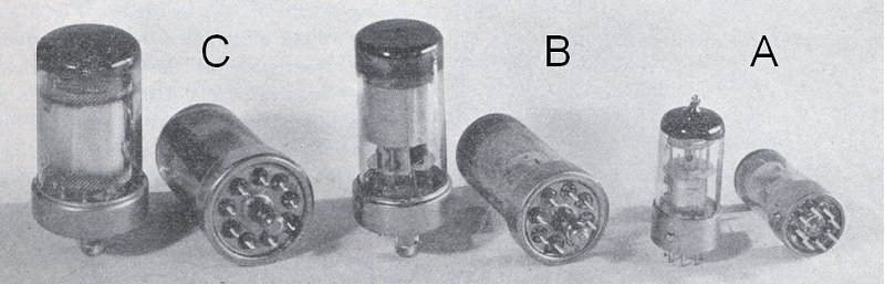
Figure 11.2 Development of the all-glass radio tube envelope just before and during the war. The three generations are designated in Philips terminology as A, B, and C type technology.
During the war Philips developed two smaller versions of the all-glass tube. In Philips terminology the EF50 envelope with dimensions 62x38 mm and 9 pins was referred to as C-type technology. A slightly smaller version, referred to as B-type technology measured 65x32 mm for low-power tubes and 80x32 mm for power pentodes and rectifiers. These tubes still used a spigot with rim and were therefore just like the C-type tubes called ďkey-tubes.Ē Towards the end of the war a radically smaller tubes was introduced which had a diameter of 23 mm and variable lengths of 52, 61 or 70 mm depending on dissipation. These tubes, which were fabricated in what was called A-type technology, had eight pins, equally spaced and used a small ďpimpleĒ on the rim of the tube to lock it into position. These tubes became known as ďRimlockĒ tubes. The technology behind the development of these technologies is fascinatingly described in an article by Alma and Prakke in the ĒPhilips Technical ReviewĒ of October 1946 [16].
In parallel to these developments at Philips, which had been cut of from (detailed) information on the developments going on at the allied side, the tube industry in the U.S.A. developed also a simple technique for the fabrication of small tubes for use in military equipment, the so called ďMiniatureĒ envelope. The Miniature tubes had a diameter of 17 mm and used 7 pins. The correct position of the tube with respect to the tube-base was found by placing seven pin on a circle equally devided to provide room for eight. Since the tubes were extremely light, no special locking system was needed; the contact pressure on the springs in the tube-socket was sufficient to secure the tube.
After the War, Philips introduced what they called the “A” technique envelope. It was slightly larger than miniature, with eight one-millimeter thick chromium-iron pins uniformly distributed along the circumference of a circle. Correct position and securing were both obtained by means of a “pimple” on the envelope which fitted into a slot in a ring on the tube-holder (“Rimlock”). The envelope and the base were not sealed but “glued” together with a washer of low-melting glass-enamel, so that the shape of the envelope remained unaffected by sealing.
Klaas Rodenhuis recollects an amusing anecdote from around this period [47]. During the war, a group of engineers at Philips had worked on a competing metal tube concept. In an attempt to eliminate the expensive projection welding, somebody had had the cleaver idea to give both the base and the metal envelope a conical shape in such a way that they would fit snugly over each other. After evacuation the two parts would form a tight fit. Apparently the idea worked, so that a decision had to be made which concept to pursue. This decision was made by Frans Otten, the president of Philips who had just returned from exile. Today it seems unimaginable that the president of Philips should be involved in a decision on such a technical detail! The meeting was held, and Otten entered. After a short technical explanation by both camps, Otten asked ‘And gentlemen, which concept is cheapest?’ Everybody had to admit that the glass concept was cheapest. ‘Fine,’ Otten answered, ‘in that case we will drop the metal tube concept, good afternoon gentlemen!’ That is how decisions were made those days!
During the Korean War, in 1951, endeavors were made to standardize the radio tube techniques used by the NATO members. The result was the NOVAL technique (nine pins in a circle providing room for ten). This tube was equiped with three-electrode lead-ins like the ”miniature“ tubes. Philips, however improved the shape of the envelope by sealing the tube base upwards. It is typical of technical progress in mass production that this technique, owing to its simplicity and logic design, has been universally accepted in spite of advertizing arguments such as ”it shows more“, ”it looks stronger“, which could be put forward in favour of other designs. Once this version had been chosen for nearly all types, the only difference being the length of the envelope, mechanization could be furthered. Machines were designed to weld the three-piece electrodes together at a rate of about 10,000 per hour, to press these electrodes into the glass base (Fig. 6.8) and to make envelopes of tube glass and to seal on stems at a reate of 2500 per hour. Thus it became possible to turn out a relatively compact unit for production of about 2,000,000 radio tubes per year. These machines were installed in Philipsí and Philips-supported factories in twelve different countries spread over the world.
It is beyond the scope of this page to give an account of the history of the Battle of Britain, there are on the internet many excellent recources available on that topic (e.g. [42], [43], [44].) Despite the superiority of the Luftwaffe, both with respect to number of aircraft, as well as the number of pilots, there is a consensus amongst historians that Germany could not have won the Battle, simply because the losses on the side of the Germans, who were fighting a battle far from their bases over hostile territory, were too high. Without air superiority the invasion of Britain (“Operation Sealion”) wouldnít stand a chance due to the superiority of the British Navy.
Throughout the battle the Germans greatly underestimated the size of the RAF and the scale of the British aircraft production. At the same time, across the Channel the Air Intelligence Division of the Air Ministry consistently overestimated the size of the German Luftwaffe. In the end the RAF, not the Luftwaffe proved to be a robust and capable organization which was to use all the modern resources available to maximum advantage. The Victory of the English in the Battle-of-Britain meant the first military defeat for Hitler. It greatly boosted the moral of the British People, and it convinced the US that Britain would survive and should be supported in every way possible. As a result Britain could become the base from which the liberation of Western Europe was launched. Despite the, according to historians, inevitable outcome of the battle, it was only won after after suffering enormous human losses on both sides. On the British side 544 aircrew were killed, on the German side 2,698. Total British civilian losses from July to December 1940 amounted to 23,002 dead and 32,138 wounded. On a single raid in December 1940, almost 3000 civilians died.
In the outcome of the Battle, Radar and Downingís intricate system to integrate it into Fighter Command played a decisive role. The EF50 and the Pye strip in which it made its star performance, turned Radar from a “research instrument” into a system that could be reproducibly mass produced at high quality, exactly Trompís mission. It is impossible, and also unnecessary to estimate to which extend this contributed to the outcome of the Battle. It is enough to end by quoting Taffy Bowen, one of the key persons involved in the development of Radar and its deployment during the War:
| to top of page | back to homepage |
In researching a story like this, there are always a number of leads that are not followed-up. Most of the time the reason is just lack of time, or because I live too far away from the sources. At this point I thought it a good idea to call in the help of the readers of this page. If you like to contribute to this fascinating story, and if you happen to live near one of the sources and if you have the time, here is your chance! Your help is highly appreciated!

| to top of page | back to homepage |
The following people are gratefully acknowledged for their contributions: Ir. Klaas Rodenhuis; Mr. John Liffen, Mr Rory Cook and Mr. Doug Millard all from the Science Museum; Marc Rensen and Marianka Louwers from Philips Company Archives; Mr. Nicholas Stanley, Cor Moerman from The Dutch Ham Radio Museum ďJan CorverĒ; Mr. NoŽl van Mossevelde from The Philips Museum, Mr. Mark Frankland, Mr. Kees Wissenburgh Conservator of the Valve collection of the Study Collection of the Faculty of Electrical Engineering of the Technical University of Delft, Dr. F. Prakke, Hr. D. Alma, ir. Hoefgeest, A.M. Tromp, T.J. Tromp, Dr. A.E. Pannenborg; Dr. W.H.P.M. van Hooff and Eric Geelen from the Technical University of Eindhoven, Corrie Pancken of Philips Research
| to top of page | back to homepage |
Yours truly in front of the original equipment used by Watson-Watt and Wilkens to demonstrate the principle of Radar in 1935.
It is safely kept at the Science Museum in London (on the fourth floor at the rear). London 17th October 2012