|
|

|
An E1T raised from the dead The making of the E1T |

|
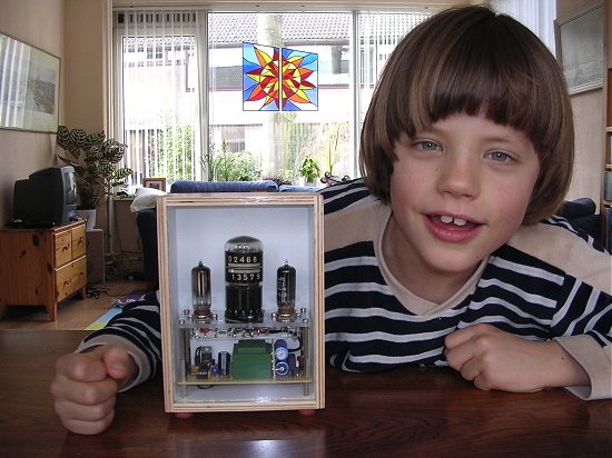
To me the E1T counting tube is unmistakably one of the most intriguing tubes ever made. It was invented and developed into a product by Philips in the period 1946-1954. On one of my other pages I have posted an in-depth study of it’s origins. It has long been my whish to build a clock with this wonderful device.
One of the problems of making a clock from this tube is it’s limited lifetime. The E1T was designed for high-speed counting in measurement equipment. This was achieved by using an electron beam as opposed to a glow discharge as used in the competing decatron. This implied the use of a filament heated cathode, and unfortunately even the best filaments have a limited life expectance of ca. 10.000 hours (1.2 year).
 One of the ways to improve the life expectancy is to reduce the filament temperature. Obviously this will reduce the emission, and hence the beam current. It appears that for this application, where only low speed counting is required, a lower beam current is no problem at all. The other obvious measure to improve the life time of the tube is to simply switch it off when it is not used. In general, the frequent on/off switching of filament heated tubes is not a good idea. A cold filament has a significantly lower resistance than a heated one. This will cause a high start-up current resulting in high mechanical stresses during the heat-up phase. This is the reason that many tubes (and light bulbs) die the moment they are switched on. In this clock the filament is not completely switched off, but kept heated at a very low level, resulting in strongly reduced thermally induced stresses.
Two mechanisms determine when the tube is actually switched on and off. In the first place the user has to select one out of eight “profiles” upon initialization. Each of these profiles determines during which hours of the day the tube is switched on. If e.g. the clock is situated in the bedroom, a profile can be selected so that the tube is only switched on at night. Similarly, profiles have been defined that only switch the tube on during office hours, in the evenings etc. Additionally, it is always possible to force the tube on by pressing the control button. Each time the button is pushed the tube will stay on for an additional hour. By selecting profile “1” the clock is always off, except when the control button is pushed.
The E1T tube is rather rare, and I didn’t want to use six tubes for just one clock. Recently I built a one digit NIXIE clock for my eldest son and it was a great success. The multiplexing of the time over one tube, is a bit of a puzzle and attracts a lot of attention. So obviously this was going to be a one digit clock as well. Since for every new digit the tube first has to be reset and then count to the new value, it is especially attractive because “there is something to look at”.
| to top of page | an E1T raised from the dead | The making of the E1T | back to homepage |
In a circuit which is directly fed from the mains, the circuit is connected via a direct galvanic
connection to the mains. Before I start with the description of the clock circuit, I have to
explain why directly mains fed circuits are so dangerous, much more dangerous than circuits
that use the same high voltage but derived from a transformer.
Figure 1 Touching a high voltage circuit that is isolated from the mains
is not dangerous as long as no current can flow.
Figure 1 shows a simplified schematic drawing of the final part of the power distribution grid
that delivers the power to your home, connected to an appliance that uses a transformer.
Lets for the sake of this example assume that it is a 240V to 180V transformer used to
feed the NIXIE tubes.
In the last distribution station the high voltage from
the power grid is transformed down to e.g. 240V, the mains voltage we have in Europe.
The power is delivered through two wires. One of these wires is called the "life wire" or the
"phase wire". The return wire is called the "null" or "ground" wire. It is important to note
that at the distribution station the ground wire is connected to ground, that is the
ground that you are standing on!
Figure 2 Touching an high voltage circuit at two points closes the loop so that
a current can flow,
resulting in a painful if not lethal shock.
When any part of the circuit at the secondary side of the transformer is accidentally touched,
nothing happens since there is no path for the current to flow to ground. The entire circuit is,
although it carries high potential differences, floating with respect to ground. The situation
changes dramatically when accidentally two points in the circuit are touched (Fig. 2).
A large voltage between the points touched will give you a nasty shock or may possibly even kill you!
This is the reason why my father thought me always to keep one hand in my pocket while fiddlingaround with high voltage circuits.
The fact that the secondary side of the transformer is floating with respect to the mains
grid, makes that we can define one of the two terminals as ground and connect it e.g. to the
cassis. In this case we only need to worry about isolating the high voltage derived from the other
transformer terminal.

Figure 3 In a circuit that is not isolated from the mains, even a single touch will
result in a flow of current through the ground you are standing !
When no transformer is used, the circuit will always carry a deathly potential with respect to the real ground (Fig. 3). In this case a single touch to any part of the circuit will result in the flow of a current straight though your body to ground. This may very easily kill you! Note that in this case we have no way of knowing which terminal is connected to the live wire and which terminal is connected to the ground since this will depend on the position of the mains plug in the wall outlet. Consequently, we have no way of defining one of the terminals as a local ground. The only solution is to isolate the entire circuit!
 It is good for a moment to think of what this really means. It means that you have to treat every
part of the circuit as if it is connected to a lethal voltage with respect to ground,
even if the potential differences in the circuit are only small! This is sometimes
a little bit difficult for people to understand. I used to have a neighbor who was in the habit
of decorating his garden with Christmas tree lights. Now, instead of buying decent outdoor type
of lights he used cheap indoor lights. Being a "they don't fool me" type of man he argued:
I have 40 lights running on 240V so every light only runs on 240/40=6V, which is not dangerous at all.
Despite my repeated arguments, he was unable to see that although the potential difference across
each lamp might be as small as 6V, the potential difference with respect to ground can be as high as
240V. In other words lethal.
It is good for a moment to think of what this really means. It means that you have to treat every
part of the circuit as if it is connected to a lethal voltage with respect to ground,
even if the potential differences in the circuit are only small! This is sometimes
a little bit difficult for people to understand. I used to have a neighbor who was in the habit
of decorating his garden with Christmas tree lights. Now, instead of buying decent outdoor type
of lights he used cheap indoor lights. Being a "they don't fool me" type of man he argued:
I have 40 lights running on 240V so every light only runs on 240/40=6V, which is not dangerous at all.
Despite my repeated arguments, he was unable to see that although the potential difference across
each lamp might be as small as 6V, the potential difference with respect to ground can be as high as
240V. In other words lethal.
The idea of feeding a circuit directly from the mains is actually very old. The first radios
operated on batteries, one for the filaments and another high voltage battery for the plates
(anodes). The obvious reason was that only few houses were connected to the mains!
Since the current drawn from the anode batteries was usually very small, in the order
of mA's, these batteries only needed replacing every few months or so. Nevertheless is was cumbersome
and expensive. In the forties almost every body became connected to the mains, so mains
fed power supplies (with transformer) began to replace batteries. Directly after the war everybody
wanted a radio for an affordable price, so radio set makers were forced to cut down production
costs. One of the most expensive parts in a radio was the mains transformer. Set makers came up
with a clever trick to eliminate the transformer.
 Instead of making tubes that would run on a
filament voltage of 4 or 6 Volts, they fabricated tubes with a much higher filament voltage so that
when the filaments of all the tubes in a radio were placed in series, they could be directly
connected to the mains. An example of such a radio is the 209U from Philips (
click here to view the schematics ).
Often tube manufacturers would design a set of tubes which together would
make a complete radio while the filaments in series could be connected to the mains. Such a set of
tubes was called a "line up", a term still in use today for e.g. a set of transistors that will
make an RF power amplifier. The same system was adopted for televisions. As explained, a consequence
was that the whole cassis of the set was inevitably connected to the mains, and had to be
completely
isolated. The system was first abandoned for radios. Especially high end radios were provided
with a gramophone and tape recorder input. These inputs needed a ground connection, so that
isolation from the mains by means of a transformer was unavoidable. For television the directly
mains fed principle was maintained however throughout the whole tube area. In most modern televisions
the high voltage flyback converter transformer plays the double role of isolating power supply and
high voltage converter.
Instead of making tubes that would run on a
filament voltage of 4 or 6 Volts, they fabricated tubes with a much higher filament voltage so that
when the filaments of all the tubes in a radio were placed in series, they could be directly
connected to the mains. An example of such a radio is the 209U from Philips (
click here to view the schematics ).
Often tube manufacturers would design a set of tubes which together would
make a complete radio while the filaments in series could be connected to the mains. Such a set of
tubes was called a "line up", a term still in use today for e.g. a set of transistors that will
make an RF power amplifier. The same system was adopted for televisions. As explained, a consequence
was that the whole cassis of the set was inevitably connected to the mains, and had to be
completely
isolated. The system was first abandoned for radios. Especially high end radios were provided
with a gramophone and tape recorder input. These inputs needed a ground connection, so that
isolation from the mains by means of a transformer was unavoidable. For television the directly
mains fed principle was maintained however throughout the whole tube area. In most modern televisions
the high voltage flyback converter transformer plays the double role of isolating power supply and
high voltage converter.
From the previous section it should be clear that circuits directly fed from the mains
are in principle fine, as long as special precautions are taken for the isolation of the complete
circuit. Special 220V to 220V transformers are ideally suitable for this, but I don't have one.
Instead I use two "low-voltage" transformers back-to-back (Fig. 4a). Transformer T1 is a rather
bulky 10V/4A transformer, T2 is a much smaller 7V/0.7A type. The mismatch
between T1 (10V) and T2 (7v) is explained by considering the resistive losses in T2.
T2 is designed so that it delivers 7V under nominal load conditions. Under nominal conditions
the resistive losses cause a considerable voltage drop in both the primary and secundary
windings of the transformer. The manufacturer of the transformer
added secundary windings to compensate for these losses, so despite the 220V/7V specification,
it really is a 220V/10V transformer (Fig. 4b).
Figure 4 Isolation of a circuit from the mains is ideally done with a special
240/240 (or 110/110) isolation transformer.
By placing two normal transformers
back-to-back the same result is archived (Fig. 4a).
Due to voltage drops across the windings (Fig. 4b)
it may me necessary to use transformers with different secondary voltages.
| to top of page | an E1T raised from the dead | The making of the E1T | back to homepage |
The complete circuit is depicted in Fig. 5. The E1T obviously takes a central position in the circuit. The circuit around the E1T is directly taken from the datasheet of the E1T. The only thing I changed a bit were the voltages. I used the E1T tester that I described in one of my other pages to determine the operating range of the tube. It appeared that as long as not the maximum counting speed is required, significantly lower supply voltages can be used. The tube appeared to operate reliable on an anode voltage as low as 200V
and a filament voltage of 4 to 5 V. The advantage of a somewhat lower anode voltage is that also a lower pulse amplitude can be used.
Figure 5 Complete circuit diagram of the Single digit E1T tube.
click here to download a pdf file
It was one of the challenges to keep the power supply of this clock as simple as possible. One way of doing that was to take the high voltage directly from the mains without using a transformer. Normally, the transformer also acts as a low pass filter, suppressing any high voltage transients and spikes that pollute the mains. Instead I used a VDR as a first defense against any high voltage spikes. After double sided rectification by bridge Br1, capacitors C10 and C11 smooth the high voltage. C10 and C11 have been placed in series to reduce the voltage over each capacitor. The voltage divider formed by R19 and R20 makes sure that the total rectified mains voltage is divided equally over C10 and C11.
The most common way to reset the E1T is to interrupt the anode current. The standard way of doing that is to pull control grid g1 negative. In the standard circuit diagram g1 is connected by a capacitor to a one-shot pulse generator. The negative falling edge of the pulse will cause a negative spike on g1, interrupting the anode current and resetting the tube. In this clock I wanted to switch of the tube completely during display cycles. Doing that by making the control grid g1 negative would require an additional negative supply voltage, which was something that I didn’t want to do. Instead, I decided to switch of the high voltage supply completely. This has the additional benefit that it switches of the voltage regulation tubes that I have used in the voltage stabilization circuit, increasing the life expectancy of the tubes. The high voltage switch was implemented using high voltage npn and pnp transistors T5 and T6 in a straightforward circuit configuration.
Figure 6 Principle of the voltage regulator circuit: A) Direct stabilization with voltage regulation tubes, B) The same circuit with an emitter-follower buffer, C) Alternative circuit with zener diodes.
For correct functioning, the E1T requires a stabilized anode voltage. Since I had a whole bunch of voltage stabilizer tubes lying around, I wanted to use these tubes for the stabilization. Anyway the tubes glow very nicely in the dark when switched on. By using a 90C1 and 150B2 in series a voltage of 90+150=240V is obtained. From experiments with my E1T tester is was clear that this is more than enough for an E1T to function correctly. The simplest way to use the stabilization tube is depicted in Fig. 6A. The tubes have been designed in such a way that once ingnited, the voltage drop over the tubes remains more or less constant over a fairly large current range. For the circuit of Fig. 6A to function properly however, the current through the tubes should be (much) larger than the current drawn by the E1T. This would mean that the current through the tubes would have to be in the order of several mA. Although the tubes are specified to these currents, it is rather on the high side, reducing the lifetime of the tubes. By adding a high voltage transistor it is possible to run the stabilizer tubes at much lower currents. The BF487 in Fig. 6B is used in what is called common-collector or emitter-follower configuration. In this configuration the transistor is used a current amplifier. The current flowing into the base appears (1+hFE) at the emitter. So assuming an hFE (hFE or Beta is the DC current gain) of 100, this means that an emitter current of 1mA requires a base current of only 10uA. It is now possible to bias the stabilizer tubes at 1 mA or less. Since the emitter-base diode is forward biased, and the voltage drop over a forward biased junction is ca. 0.6V, the voltage at the emitter equals the base voltage minus 0.6V. For the high voltages used in this circuit we can neglect the voltage drop of 0.6V and we simple say that the emitter voltage equals or follows the base voltage. In stead of using these nice stabilization tubes, it is also possible to stack normal zenerdiodes to a value of 220-240V,
Figure 7 Principle of the filament standby circuit.
For the low voltage supplies I used a transformer with two 5V secondary windings in series. The two windings in series give rectified give the 12V required for the counting pulse. A 87L05 stabilizer is used for the 5V supply for the PIC controller. The circuit used to put the filament into standby is explained in Fig. 7. Figures 7 b1 and b2 depict the situation when transistor T is switched off. In that case only during the first phase of the mains voltage a current will flow though the filament, so that effectively the filament is running on 2.5V. When T is switched on (Fig. 7 c1 and c2), a current will flow through the filament during both phases resulting in an effective filament voltage of 5V. In reality the effective filament voltage is slightly smaller due to the voltage drop over the diodes. It appeared that a good E1T tube with a good emission would still function perfectly on a filament voltage of 2.5V.
As usual the 50Hz mains frequency is used for the timebase of the clock. Just as in almost all of my clocks I have used two opto-couplers to detect the positive and negative phases of the mains frequency. Like in the clock I made for Geert, the 50Hz signal is reconstructed by a flip-flop implemented in software. The 12f675 uses it’s internal 4MHz oscillator. The E1T requires a count input pulse with steep rise and slow fall times. This pulse is generated by the pulse shaper circuit consisting of T1 and T2. When output GPIO2 of the 12f675 becomes high T1 will start conducting. This will pull the base of T2 low, so that T2 will be driven into saturation, resulting in a steep rise of the count pulse. When GPIO2 becomes low again, T2 is switched of and the input of the tube is pulled down by R5. The high value of 1 Mohm ensures a slow fall time of ca. t=RC=1E-9*1E6=1 ms.
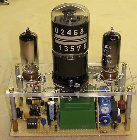
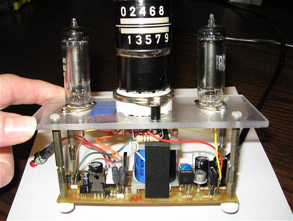
Figure 8 The complete clock still without case.
Figure 8 gives an overview of how the clock was built up. The relatively small circuit lends itself for a compact realization. I want to stress again here that not withstanding the fact that a transformer is used, the entire circuit of the clock is connected directly to the mains. Touching any part of the clock may case a potentially lethal shock. Make sure that an isolated case is used for the clock. Use a push button that is specified for 240V. Special care was taken to isolate the screws used to fix the PCB in the box from the mains. As can be seen in the photograph of the bottom side of the PCB the copper islands around the screws and between other points carrying high voltages were removed. This can be easily done by sticking the point of a welding iron in the hole. A small twist and a pull removes the copper island (as least for these PCBs).
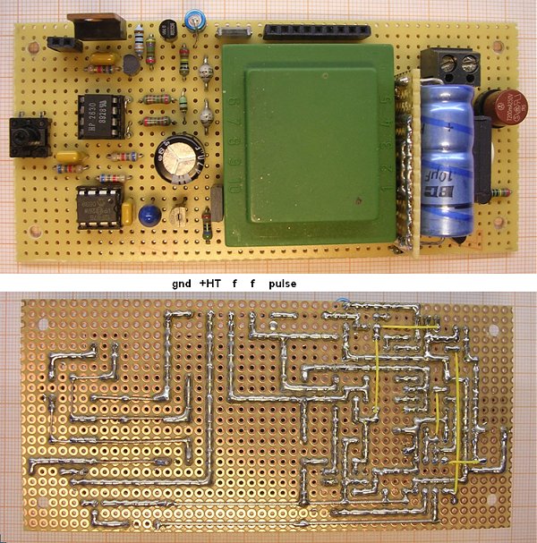
Figure 9 Front- and Backside of the PCB holding the silicon part of the circuit.
The largest part of the clock was built on a small piece of breadboard. Whereas the digital part of the circuit was built on a PCB, the circuit around the tubes was built on the “traditional way” meaning with air-bridged components stretching from one tube socket to another. It was really a pleasure to build a circuit which is as small and compact as this clock.
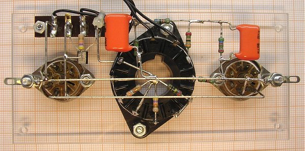
Figure 10 The tube section in a conventional "air-bridge" construction.
| to top of page | an E1T raised from the dead | The making of the E1T | back to homepage |
The program for the E1T clock basically consists of a main program and an interrupt service routine which is called every 200 µs on an interrupt generated by a roll-over from timer0. Figure 1 schematically depicts this construction with on the left the main program and on the right the interrupt service routine. The main program takes care of the initialization of the clock and it controls the E1T driver routine so that the time is displayed on the tube.
Figure 11 The structure of the firmware. On the left we find the mainprogram, on the right the interrupt service routine and its components. The most important flags and bytes that are used for the communication between the program components have been indicated.
The interrupt service routine “int_200us”, consists of seven subroutines that are called in succession every interrupt. Fig 11 summarizes how the different subroutines communicate with each other and the main program via flags (bits)
and variables (bytes). The routine flipflop emulates in software, the hardware set-reset flip-flop that reconstructs the 50Hz signal from the output of the two opto-couplers. The reconstructed 50Hz signal is available from the output bit “FF”.
Figure 12 Principle of the 50Hz filter.
The “FF” bit is input for routine “filter” which removes any transients from the 50Hz signal. The routine searches the “FF” bit for a 0 to 1 transition. When it has detected a transition, counter “FILT50” is initialized to 90 and flag “NEW50” is set. Each next call to “filter” this counter is decremented. All input is ignored until “FILT50” reaches zero again. This takes 90*0.2ms = 18ms. So any transients or unwanted noise on the mains is filtered out during this period (Fig 12). After “FILT50” has reached zero, the routine waits for the next 0 to 1 transition.
When the “NEW50” flag is set, routine “second” decrements counter “CNT50” until fifty periods have been counted. The routine then sets the “NEWSEC1” and “NEWSEC2” flags to signal a new second. The “NEWSEC1” is used by the time keeping routine “time” while the “NEWSEC2” flag is used by the main program to time the displaying of the different numbers on the E1T tube.
As already mentioned the processing of the actual time is done by routine “time”. The time is stored in variables: “hrs10”,”hrs1” : “min10”,”min1” : “sec10”,”sec1” in such a way that e.g. “min10” holds the tens of the minutes (0,1,2,3,4,5) while “min1” holds the units of the minutes (0-9). When flag “GOTIME” is cleared by the main program, the routine is skipped and the updating of the time stops. When a new hour is detected flag “NEWHR” is set. This flag is used by the”dimmer” routine.
Routine “inkey” processes the pushbutton. It uses counter “keycnt” to debounce the signal from the pushbutton. When a new valid signal from the button is detected, the “NEWKEY” flag is set. This flag is processed by the main program. All the flags (“FF”, “NEW50”, “NEWSEC1”, “NEWSEC2”, “NEWKEY”, “NEWHR”) need to be reset by the receiving routines or the mainprogram. The remaining two routines that are called by the interrupt service routine “int_200us”: “digit” and “dimmer” are discussed in the next two sections.
| to top of page | an E1T raised from the dead | The making of the E1T | back to homepage |
The driver routine “digit” takes care of displaying the number provided in variable “DIG_CNT” on the E1T. Its functionality is best displayed by Fig. 13.
When a new display cycle is started, the routine first resets the E1T by removing the anode voltage. Next a number of counting pulses corresponding to “DIG_CNT” is applied to the tube so that it counts to the desired number. The length of each step in Fig. 13 is approximately 25 ms so that the actual counting of the tube can be observed.
Figure 13 Impulse sequence used to drive the E1T, related to the status byte “DIG_STAT” and counter “DIG_CNT”.
The status of the “digit” routine is controlled by variable “DIG_STAT”. When “DIG_STAT” is zero, the routine is idle, waiting for a new display cycle. The main program can initiate a new display cycle by loading “DIG_CNT” with a value that is twice the value to be displayed (!), and by making “DIG_STAT”=1. As long as “DIG_STAT” is zero, the delay counter “DIG_DEL” is reloaded to the initialization value “DIG_SPEED” (128). Only when “DIG_STAT”>0, the delay counter is used to count down the number of calls to the routine, so that only every “DIG_SPEED” calls the next action is undertaken.
Figure 14 Flow diagram of the E1T driver routine “digit”.
The routine is essentially a state machine with the state stored in “DIG_STAT”. The following states are defined “DIG_STAT”=0 idle, “DIG_STAT”=1 reset pulse, “DIG_STAT”=2 delay after reset pulse, “DIG_STAT”=3 count pulses (Fig. 13). The working of the routine is explained in the flow diagram depicted in Fig. 14. It is pretty straight forward. The only thing that needs so explanation is how the counting pulses are generated. This is done by toggling the output bit. After value_to_be_displayed*2 toggles, the E1T displays the correct number. The simple construction eliminates the need for an additional state construction that would be needed otherwise, to remember if the pulse was to be made high or low. When the tube has counted to the value to be displayed, “DIG_STAT” is reset again, signaling that the routine is idle again.
| to top of page | an E1T raised from the dead | The making of the E1T | back to homepage |
To increase the life of the tube, there is as already explained, the possibility to switch the tube to a standby position when it is not used. Two mechanisms determine when the tube is actually switched on and off. In the first place the user has to select one out of eight “profiles” upon initialization. Each of these profiles determines during which hours of the day the tube is switched on.
Figure 15 gives an overview of the profiles that have been defined.
Figure 15 The profiles that have been pre-defined.
Additionally, it is always possible to force the tube on by pressing the control button. Each time the button is pushed the tube will stay on for an additional hour. So suppose the clock is off, then pressing the button four times will switch the tube on for four hours. The pressing of the tube is detected by a routine in the mains program. Every time the button is pushed, “HRS_ON” is incremented. The routine “dimmer” switches the tubes on when “HRS_ON” > 0 and decrements “HRS_ON” every hour until it reaches zero.
Figure 16 Flow diagram of the filament saver routine “dimmer”
Figure 16 depicts the flow diagram of routine “dimmer”. The routine first checks if “HRS_ON”>0. If this is the case the tube is always switched on, regardless the selected profile. Note that, since only the “digit” routine can switch the high voltage on, the “dimmer” routine just sets the “HV_OK” flag to signal the “digit” routine that it can turn the high voltage on (Fig. 14). The routine next checks the “NEWHR” flag to see if a new hour has elapsed. If this is the case “HRS_ON” is decremented. If on the other hand “HRS_ON”=0 the clock follows the profile to decide if the tube is to be switched on or off.
| to top of page | an E1T raised from the dead | The making of the E1T | back to homepage |
The main program consists of four parts. In the first part (power up) the filament is switched on in the reduced power state. The program next waits for thirty seconds before it switches the filament fully on. If the push-button is pressed during the warm-up period, the filament is switched on immediately. The program next gets the profile number from the user, followed by the time in the order Hrs10, Hrs1, Min10, Min1. The clock is then halted, and starts when the button is pressed again. The way the data is entered is the same as for all my clocks: the tube counts the numbers, and a number is entered by pressing the push-button.
The main program is rather straightforward. It uses two subroutines: “getnum” and “wait”. Routine “getnum” inputs a number from the user. The input to this routine is a maximum number (“MAXNUM”) supplied in W. The routine next displays, at seconds intervals, the numbers 0,1,2,3,4,....MAXNUM,0,1,2,3,4,....MAXNUM,0,1, etc. until the push-button is pressed. The number that was in the display when the button was pressed is returned in W. The routine “wait” literally waits for a new second by waiting until “NEWSEC2” becomes true. The routine is used by the main program when it waits for the next digit to be displayed when it displays the time. When the push-button is pressed while the routine is waiting, “HRS_ON” is incremented.
| to top of page | an E1T raised from the dead | The making of the E1T | back to homepage |
The compressed file which can be downloaded here , contains the following files:
| to top of page | an E1T raised from the dead | The making of the E1T | back to homepage |
Probably the poorest quality video on YouTube,
but my camera is just not
sensitive enough.
It does however give a good idea of how the clock
shows the time.
The time indicated is 14:39
Guus Assmann’s version of the E1T clock.
This is the PCB Guus designed for the E1T clock.
Click here or on the picture to download a zip file with the artwork.

Early advert for Philips radio tubes from “Radio Nieuws” 1927.