At the peak of production in the fifties, Philips produced about 200 million radio tubes a year. It was an enormous industry, in which thousands of people were employed. Over a period of forty years the science and craftsmanship of radio tube manufacturing had been mastered to the level of perfection. It is almost inconceivable, that apart from half a shelf of books in the library and a few hundred forgotten reports, all this knowledge and craftsmanship has almost vanished today. Together with this knowledge, also all the non-technical aspects of this period are fading away: the people who played an important role, how the work was divided and organized, the anecdotes etc.
One of the side-effects of really great inventions, especially those that from the start were being recognized as important, is that they are usually very well documented. The invention of the transistor for example has stimulated scores of gifted writers and journalists to delve into all the aspects of this important event. Consequently, we now have access to many excellent books which give us a fascinating overview of the semiconductor research at Bell Labs during those years. Apart from the technical details, today we know about the life and personalities of the principal players, and the many stories that bring the whole period to life.
In this limited investigation, I have tried to recreate a glimpse of the research and development on radio tubes at Philips. Apart from the pentode, which was invented by Tellegen in 1926, the research at Philips unfortunately does not know an invention that can compare with the transistor. Instead, the focus of my search is a more moderate invention: the E1T counting tube.
The first reason for this choice is rather personal. When I was still a child, my father once gave me an old E1T tube to play with. I had of course no idea what it was, but the strange tube fascinated me. The second reason is that a large group of enthusiasts all around the world has developed a renewed interest in all sorts of counting- and indicator tubes for the use in nostalgic ōretro-clocksö. In that sense the E1T is still very much alive, and undoubtedly many people will be interested in its origins.
Figure 1. The working principle of the dekatron on the left is based on the transfer of a glow discharge from one cathode to the next. The E1T scaler tube on the right is based on the deflection of an electron beam.
During the forties and fifties there was a demand for accurate high speed counters for industrial applications and measurement equipment such as frequency and radiation counters. This resulted in the invention of the dekatron counting tube published by R.C. Bacon and J.R. Pollard from Ericsson Telephone Research Laboratories, England in 1950 [28]. A dekatron tube consists of a circular arrangement of rods, the cathodes, around a circular anode. On one of the cathodes a glow discharge is invested. By means of a two phase clock that is applied to two guide electrodes, the glow can be transferred to the next cathode. Since this process relies on the ignition of a plasma, the maximum counting speed is somewhat limited. Almost simultaneously, the work on ribbon-shaped electron beam tubes by Philips Research [13] had resulted in the conception of the E1T counting tube. In fact we find the first reference to the tube in van OverbeekÆs notebooks dated as early as the 20th of February 1946! The Philips researchers argued that since this tube relies on the deflection of an electron beam, it would be inherently faster.
The E1T is a remarkable tube. In the first place it is a miniature cathode ray tube with a Pierce electron gun, two deflection plates and a fluorescent screen. When the voltage on the deflection plates is varied, the electron beam scans over the fluorescent screen lighting one of the green windows next to the numbers. But it is more than just an indicator device such as a nixie or numitron tube. The E1T is not only an indicator, it is also a counter! Without the need for external active components it can count pulses at a rate up to 40 kHz, while counting rates up to 1 MHz have been demonstrated under laboratory conditions. So in modern day language the tube contains a memory of 3.5 bits. The memory is realized in a very clever way. The Philips Researchers placed a screen with slotted apertures in the path of the electron beam just in front of the fluorescent screen. When the beam passes a slot, one of the numbers is illuminated, though only very little current flows though the aperture. However, when the beam hits the screen in between two slots, the full bundle current is now carried by the screen. With a simple feedback circuit this current is used to adjust the voltage on the deflection plates so that the beam stays ōlockedö in one of the slot positions. By applying a short AC pulse of well defined amplitude to one of the deflection plates, the beam is forced to the next stable position. All in all a very clever construction, but not an easy one to manufacture.
I had forgotten all about the E1T tube my father had brought home for me almost thirty years when I found it again, and decided to bring it back to life again. A short description of those experiments on my web page brought me in contact with Keith Vandervelden. Keith wrote me an email starting: ōThat tube was my life when I worked at the Philips Radio tube lab 1ö. In the following email correspondence Keith provided me with many details, not only concerning the development of the E1T, but also about the organization and atmosphere at the Philips radio tube-lab. On his suggestion I came into contact with Klaas Rodenhuis, who was KeithÆs superior at that time and with relatives of other people who played in important role in the conception and realization of the E1T.
Most memorable was an interview I had with the widow of Jonker who still lives by her self in good health at the blessed age of 98 in the beautiful house the she and her husband bought more than seventy years ago! Together they provided me with a wealth of stories and photo material.
I considered it my duty to document all this information. This story is foremost about people. It does not pretend to give a complete or scientific account of the period. I have tried to place the story in the context of the origins of Philips and Philips Research, to explain how an organization and working atmosphere was created in which inventions like the E1T and many others could (and can) be made. It should be considered work in progress, I plan to add some new material e.g. on the E80T (a sister tube of the E1T) and on Lemmens, so if you are interested please check from time to time for new versions. And finally, I hope that reading it is as enjoyable for you as writing it was for me.
Incandescent electric light is the sensation at the first international
electricity exhibition
in Paris in 1881.
Two years later, in 1883, Gerard Philips graduates from the mechanical engineering
faculty of the Technical University of Delft in Holland. Gerard's father
Frederic Philips
is a banker, he runs a tobacco trading company, a coffee roasting company, a
cotton factory
and he owns a small gas company. So entrepreneurship was certainly in the genes
of Gerard
and his brother Anton. Gerard was undoubtedly fascinated by the possibilities of
electric light.
He supervises the installation of electric light on the steamer
"Willem Prins van Oranje" in Glasgow that was owned by a friend of the family.
As a result of the trip to Scotland,
he comes into contact with the great scientist Thomson, the discoverer of the electron. He works
for Thomson
for about a year. This gives him the opportunity to learn the latest novelties in
electrical
engineering [1].
Figure 2. Gerard experimenting in Amsterdam (left), the small factory that was bought in 1891 and where the production of light bulbs started.
When he returns to Holland, Gerard develops his own method for the fabrication
of
carbon filament light bulbs.
With money from his father he is able to buy a small factory
in Eindhoven (Fig. 2) and in 1891 the "vennootschap" Philips & Co is founded. The old Philips factory that was originally located at the edge of the small rural village of Eindhoven, facing the country side, survives as a museum and is now located in the very centre of the city of Eindhoven that developed around it. Production starts on a small scale with only a few hundred lamps
a day.
There is no electricity grid in those days, and the lamps are sold to hotels,
factories
etc. who have their own generators. One of these companies is ironically a
candle
manufacturer! In 1894 Philips becomes profitable for the first time.
Figure 3. Anton Philips at the beginning, and near the end of his career. He was a much loved figure both among Philips employees and in Eindhoven in general. His statue can be found in front of the railway station in Eindhoven.
Fierce competition in Europe forces Philips to lower its prices by increasing
production.
New factories are built and in 1895 Anton Philips, a gifted sales person, joins
Firm and a competition between the two brothers arises whereby Anton is trying to sell
more lamps
than Gerard can produce and visa versa. In 1900 production reaches 3 million
lamps a year.
With sales offices located in 28 cities in and outside of Europe, Philips can
compete with
its largest competitors only ten years after it was founded.
The enormous competition in the early nineteen hundreds stimulates lamp
manufacturers to
come with innovative products. None of these innovations had such an impact as
the tungsten wire lamp that was introduced by General Electric. To increase the
efficiency of
lamps it is necessary to increase the filament temperature. Carbon in
principle has
the highest melting point, but unfortunately evaporates quickly at very high
temperatures. Metal wire filaments on the other hand have a lower melting point
which makes it impossible to use them at very high temperatures. Tungsten is one
of the few metals who's melting point is high enough, but it is a difficult
material to work with. The sintering process that is developed at Philips is
difficult,
and the wires are brittle and fragile. Nevertheless, Philips decides on a full
scale
production of the new lamp, and within
a few years the number of employees increases from 400 to 2000. Philips is now the largest private employer in Holland.
Figure 4. William D. Coolidge who in 1910 invented a way to make ductile tungsten filaments.
In 1910 William Coolidge at the laboratory of General Electric in Schenectady
achieves a breakthrough by developing a method for the fabrication of
ductile tungsten wires.
The result is a wire that is much stronger than the sintered tungsten wires.
The process works by pulling wires at a high temperature from an ultra pure
tungsten
ingot through successively smaller holes drilled in a diamond. The thinnest wires
fabricated this way have a diameter as small as 10 µm [2].
General Electric surprises everybody with the introduction
of incandescent light bulbs with this "pulled" tungsten wire.
The technicians at Philips are at their wits end, and begin October 1911 Anton
Philips
sails to the US to buy the necessary equipment
and technology to also produce metal wire filaments. That same year the first
lamps
with a pulled wire are fabricated and tested!
Figure 5. Early advertisement for light bulbs with ōpulled wiresö in a typical Dutch setting.
Although the pulled wire lamps are a big improvement over the carbon and
tungsten sintered
filament, the efficiency of the lamps is still limited by the relatively low
filament
temperature. A too high temperature still results in a fast evaporation of the
filament.
It was known that if the light bulb is filled with an inert gas like nitrogen
or
argon, the evaporation of metal from the tungsten filament is strongly
reduced. The evaporated tungsten atoms are simple knocked back to the filament as
a result
of collisions with the gas atoms. However, the gas would strongly cool the wire,
reducing
the efficiency again.
Figure 6. Irvin Langmuir discovered how a combination of a gas filled light bulb with a double spiraled filament resulted in a higher efficiency.
A breakthrough is achieved by the American scientist Dr. I. Langmuir. Langmuir
had made an
extensive study of the conduction of heat through gasses. From this study he
learned that
the heat loss can be reduced if instead of a long thin wire, a short thick wire
with
the same surface is used. From an electrical point of view this is however not
desirable since
it results in a low burning voltage and high current. The brilliant
invention of
Langmuir is that instead of using a massive thick wire, he proposes to use a
double
spiraled thin wire. The spiraled wire has approximately the same heat loss as the
thick wire
but burns on a high voltage and low current. The idea is patented by
General
Electric. Philips quickly takes up this technology, and their Argon filled light
bulbs
eventually prove superior over the lamps from General Electric [2].
Figure 7. Microphotograph of a double spiraled filament. This SEM picture is made by Frans Holthuysen
This was however the second time within a few years that Philips had been taken
by
surprise by one of their competitors. The Philips brothers realize that the
innovations from General Electric are the result of fundamental physical
research.
They recognize that for the future of the company it is vital that Philips
embarks on its own fundamental research program. So an advertisement for a
scientist
with a PhD in Physics is placed in the newspapers [1].
Figure 8. Advertisement in the ōNieuwe Rotterdamsche Courantö, 23 October 1913 for a physicist who was to set-up a research organization within Philips. The text reads: ōWanted, a capable, young Doctor in Physics with good experimental skills. Write giving details of age and curriculum vitae including references to NV Philips Gloeilampenfabrieken, Eindhoven
click here to view the application letter that Holst wrote in response to this advertisement. (The handwritten remarks are by Gerard Philips)
Gilles Holst is born in Haarlem in 1886. After he finishes high-school (HBS) in
1903,
he sets out to study mechanical engineering at the ōEidgenössisch Technische
Hochschule (ETH)ö
in Zürich, Switserland. After a year he changes courses to study mathematics and
physics.
In 1908 he receives a ōDiplom of geprüfter Fachlehrer". He returns to
Holland, and
in 1910 becomes an assistant to
professor Heike Kamerlingh Onnes in Leiden [3]. Kamerlingh Onnes was an excellent
experimental
physist. His research into gases at very low temperatures enables him as the first person to liquefy
helium, and in 1913 Onnes
receives
the Nobel prize for his work. While working in Leiden Holst continues working on
his thesis
under the supervision of professor Weiss in Zurich. He receives his Ph.D. in
1914.
By that time he is already working for Philips [4].
Figure 9. Early picture of Gilles Holst, founder of Philips Research.
It is not really known why Holst left Leiden to go working for Philips.
Given the vibrant atmosphere
at the Kamerlingh Onnes lab, which was at that time world renowned, this move
was
remarkable. Possibly it was ambition: "I am to be given a whole laboratory to
equip, and I
shall carry out all manner of investigations that will teach us the formula of
the
incandescent lamp" writes the 28 year old Holst to a friend [5].
Figure 10. The NatLab at the ōKastanjelaanö in 1923.
Gerard Philips expects Physical Research to provide a different viewpoint and to yield new insights that will enable the company to become less dependant on external knowledge, and on patents owned by other companies. The first years most of HolstÆs time is spent on routine jobs such as trouble-shooting, testing and measuring. In this he works together with the small chemistry lab of Hamburger. During these years he makes a careful study of the state-of-the-art, and the phenomena related to electric light. He publishes the result of this study in a small, but very readable little book titled ōLichtbronnen en hare eigenschappenö (ōelectrical light sources and their propertiesö). HolstÆs aim is clearly to search for new light sources. In particular the phenomena of gas discharge and fluorescence had captured in interest. In the next years many papers and patents related to gas discharge devices are published. To keep in touch with the research work, Gerard Philips visits the lab every Saturday morning at 11 a.m. [5].
Holst organizes the research along principles that were summarized by Casimir in the form what is within Philips Research known as ōthe ten commandments of Holstö:
Engage competent scientists, if possible young ones, yet with academic research experience.
Do not pay too much attention to the details of their previous experience.
Give them a good deal of freedom and give a good deal of leeway to their particular preferences.
Let them publish and take part in international scientific activities.
Steer a middle course between individualism and strict regimentation; base authority on real competence; in case of doubt prefer anarchy.
Do not split up the laboratory according to different disciplines, but create multi-disciplinary teams.
Give the research laboratory independence in choice of subjects, but see to it that leaders and staff are thoroughly aware of their responsibility for the future of the company.
Do not run the research laboratory on budgets per project and never allow product divisions budgetary control over research projects.
Encourage transfer of competent senior people from the research laboratory to the development laboratories of product divisions
In choosing research projects, be guided not only by market possibilities but also by the state of development of academic science.
These rules were strictly obeyed until the eighties when ōcontract researchö made its entry, thereby violating the eighth commandment. The nature and organization of the work at Philips Research has certainly changed since Holst defined his commandments, but so has the world! Nevertheless, Holst would be pleased to see that the researchers in ōhis NatLabö still enjoy a relatively high degree of freedom.
Figure 11. From left to right, van Mesdag, a member of the Philips board, Gerard Philips, Holst and Anton Philips. This photograph was taken 25 October 1933 on the occasion of the fiftieth anniversary of GerardÆs obtaining his engineering degree. He was invited to visit the NatLab by Holst and Anton.
Slowly, Philips moves into new markets such as X-ray and radio. The physics lab proved indispensable for Philips when it came to providing new knowledge about technologies with which it was unfamiliar, but which are necessary if it was to step into new markets. By know the Physics lab had become known as the NatLab. An abbreviation of ōNatuurkundig Laboratoriumö (ōPhysics Laboratoryö). To accommodate the diversification policy of Philips it was decided to expand the NatLab organization. The first step was to move the laboratory to a new and well equipped building and to take on new and highly educated personnel [4].
Figure 12. Hendrik Kramers, Otto Stern, Arnold Sommerfeld, Albert Einstein and Gustav Hertz (from left to right) all visited the NatLab in the thirties and forties and gave lectures on the latest developments in physics. Gustav Hertz was employed at the NatLab for a few years.
This is in the early years of the NatLab not straightforward. The phenomenon of an industrial research organization was something completely unheard of in Holland in those days. For a Dutch scientist a carrier in a commercial organization was highly unusual. It was for Holst therefore important to position the NatLab as a scientifically recognized research laboratory. A breakthrough is achieved when Holst is able to hire the by then well known German physicist Gustav Hertz. Hertz worked on the theory of gas discharge and later received a Nobel Prize. In 1920 Paul Ehrenfest gives a series of lectures
on some recent physics topics. His example is followed by famous scientists such as James Frank, Otto Stern, Albert Einstein, Hendrik Kramers and Arnold Sommerfeld.
Figure 13. The original lab at ōthe Kastanjelaanö was expanded several times. In the fifties it moved to its present location in Waalre, just south of Eindhoven.
Over the years the NatLab provided Philips with important inventions and patents resulting in innovative and often highly profitable products. The high-pressure mercury lamp, ferroxcube, delta modulation, plumbicon TV pickup tube, video long play, the pushed-out-base transistor, LOCOS, IIL, NiMH batteries, Compact cassette, compact disk, Incredible sound, Optical Mammography and Silicon-On-Anything are all NatLab inventions. Ironically, the first really very important invention of the NatLab, the pentode, had nothing to do with lighting, but rather paved the way for a rapid and extremely successful expansion into a completely new market: radio.
In August 1917, in the middle of the First World War, a German seaplane is
forced to
make an emergency landing in the territorial waters of neutral Holland. When
military officials salvage the plane, they discover a radio receiver
containing two radio tubes made by Telefunken [6]. The military are fascinated
by the possibilities of this new invention and they turn to Giles Holst to see
if Philips is willing to produce a small quantity of these tubes for
experiments. Holst declined the request on the argument that Philips did not see
any commercial interest in the device! Note that by this time Philips was
already a 25 year old company with a single mass produced product: light bulbs.
As a result the military turn to another Dutch light bulb manufacturer the
ōN.V. Metaaldraadlampenfabriek Hollandö. At the end of November that year they
produce the first radio tubes fabricated in Holland.
Figure 14. The Dutch radio pioneer Steringa Idzerda and his transmitter. Idzerda played an important role in the resistance against Germans during the second World War. He was shot by the Germans in 1944.
In 1918 the Dutch radio pioneer Hanso Henricus Schotanus a Steringa Idzerda
founds the ōNederlandse Radio-Industrieö (NRI). Whereas Philips still
considered the radio to be a toy for the military, Idzerda realizes the
potential of this new medium for the large public. For the fabrication of the
necessary radio receivers Idzerda needs several hundreds of radio tubes per
year. Idzerda first turns to the Metaaldraadlampenfabriek Holland who had
already fabricated radio tubes for the military. They were however tied to the
military by confidentiality contracts. So Idzerda again tries to persuade
Philips to produce the radio tubes he so desperately needs. Idzerda is lucky,
he is able to persuade Gerard Philips who personally orders Holst and his
staff to make the so called ōthree electrode lampsö.
Idzerda proudly advertises the tubes in ōRadio-Nieuwsö January 1919 under the
name ōIDEEZETö.
Just imagine for a moment that Philips would have acknowledged the original
request from the military a year before. In that case Philips would have been
tied down by the confidentiality contract!
Figure 15. The ōIDEEZETö, the first radio tube to be made by Philips. Note how the sockets used for light-bulbs were used for the electrode connections. The picture on the left shows the very first advertisement for a radio tube made by Philips and sold by Idzerda taken from ōRadio Nieuwsö January 1919. The advertisement proudly mentions that already 1450 tubes have been sold. Click here to see the advertisement in more detail.
The cooperation between Philips and Idzerda continues the next year with
experimental transmissions between the NRI in The Hague and the NatLab in
Eindhoven. Philips quickly loses interest when Idzerda starts with public
transmissions of news and music programs. In 1924 Idzerda is forced to stop his
transmissions due to lack of funds. The annual production of radio tubes in
those years is still very limited. In 1921 only 321 radio tubes and 100
transmission tubes are fabricated in the NatLab that was still located on
the fourth floor of the tube fabrication plant in those days.
Figure 16. Balthasar van der Pol was in 1917 already a well known authority on radio as shown by this article from Wireless World of 1917.
In the following years, however, the demand for radio tubes strongly increases.
The orders are placed by radio stations. This is explained by the fact that
radio stations in those days exploited the fabrication of radio sets. The
increase in demand arouses the interest of Anton Philips. By bundling orders,
sufficient volume is created to justify the building of a dedicated radio tube
fabrication plant. In August 1922 the carbon filament light bulb fabrication
moves out of the fourth floor of the plant on the Emmasingel to make place for a
radio tube fabrication facility. Before the end of that year the location is again too small. Production at that time had increased to 1000 radio tubes per
day! The production site increasingly turns to the NatLab for help in technical problems related to the fabrication of radio tubes. In order to extend the scope of the research to radio tubes, Holst hires the physicist dr. Balthasar van der Pol. Van der Pol, who for two years had worked in England for J.A.Fleming and J.J.Thomson, was at that time already well known for his work on radio [7].
Figure 17. Bernard Tellegen (27 June 1900 ¢ 30 August 1990) was one of the first members of van der PolÆs group. In 1926 he invented the pentode. The patent on the pentode gave Philips during decades a monopoly position on the European radio tube market. Until a few months before his death, Tellegen used to visit the NatLab every week. After visiting the library he used to enjoy an extremely sober lunch.
During his first years at the Research Lab, van der Pol concentrates on the
development of radio tubes that operate at a reduced filament current, the so
called: ōMiniwattö series. By 1924 a technique is developed to coat the
filaments of radio tubes with a barium oxide layer. The barium oxide lowers the
work function, and in that way strongly increases the electron emission. By that
time 9 of the 16 employees of the research lab work on the development of radio
tubes. Two years later the first member of van der PolÆs team, Bernard Tellegen
at the age of 26, invents the pentode (Fig. 17). It was possibly one of the greatest inventions of the NatLab ever. The first pentode is the B443S. In 1927 Philips produces its first radio receiver with a pentode in the output stage.
Johan Lodewijk (Hans) Jonker was born on the 19th of March 1901 in Den Haag (The Hague). From Sept. 1915 to Sept. 1920 he attended the H.B.S. High School in Den Haag. Being born five years before the invention of the triode by Lee De Forest, it is easy to understand how these revolutionary new technological developments must have appealed to the young Jonker when he was in his teens. According to his widow he was always experimenting with wires and other electrical stuff. Besides this, Jonker is also artistically gifted. He makes beautiful pictures and drawings, and for some time he is tempted to pursue a career in the arts. After his father advices him that ōunless you are very good, it is difficult to make a decent living in the arts,ö he decides for a scientific career.
After high school he goes to Delft to study electrical engineering at the Delft University of Technology. During his studies he develops an active interest in electronics and he publishes several papers in ōRadio-Nieuwsö [14]. ōRadio-Nieuwsö (Radio News) was a periodical for radio pioneers and amateurs that was published between 1917 and 1933. Copies of ōRadio-Nieuwsö are still kept in the antiquarian book department, ōthe tresorö (archive) of the central library at the University of Delft. His first contribution to ōRadio-Nieuwsö dates from 1920 written at the age of 19. It discussed the fabrication of electrolytic rectifiers. The second paper, two years later, discusses a universal measuring tool.
After he received his masterÆs degree in January 1925 he takes up a job at the cooperative sugar factory ōDinteloordö in the small town of Stampersgat near the city of Roosendaal. For a young man who grew up in the sophisticated area of Den Haag and Delft, the transition to the desolate agricultural area of Dinteloord must have been a shock. It is therefore no surprise that in slightly more than a year, in September 1926 he returns to Den Haag for a position at the Dutch Patent office [9].
Figure 18. Jonker worked at ōSPLENDORö on the development of radio tubes from July 1927 until January 1939. In the right picture Jonker is the third person seated from the left.
At the age of 26, Jonker takes up his third job in July 1927 when he becomes an employee of the ōSPLENDORö Light-bulk factory in Nijmegen. In 1919 the ōGloeilampfabriek Nijmegen NVö (lightbulb factory Nijmegen) was registered and production was started in a small factory at the Van Gentstraat 70-74 in Nijmegen. In 1926 the brand name SPLENDOR was introduced. Under this name the company was well known in Holland for its high quality products. Eventually, due to competition from the Far East, SPLENDOR was forced to close its factories in 1977. According to JonkerÆs file in the NatLab HR Department archive, Jonker was in charge of radio tube development and production at Splendor [9]. The activity certainly can not have been a large one since very little is known about SPLENDOR radio ōlampsö anymore.
Figure 19. This enormous white building housed the radio tube fabrication division. All radio tubes fabricated by Philips in Holland were made here. The building is known in Eindhoven as ōde witte dameö (the white lady). The photographs show the white lady from both ends of the Emma single. The arrows show the floor where the tube lab was located and where the E1T was fabricated.
Figure 20. A Photograph taken from JonkerÆs PhD thesis depicting the ōrubber-sheetö electron trajectory simulator.
One way or the other normal life is resumed, and in the middle of the second word war in occupied Holland on the 5th of June 1942, Jonker defends his PhD thesis at the technical university of Delft. The title of his thesis is ōStroomverdeling in versterkerbuizenö (Current distribution in amplifying tubes). The main topic of the thesis is the calculation of electron trajectories in electron tubes. Except for some very simple configurations, it was at that time not possible to calculate the exact trajectory of electrons in an arbitrary electrode configuration. In order to simulate the electron trajectories, Jonker and his workers create a mechanical simulator consisting of a rubber foil suspended in a metal frame (Fig. 20, 22). The height of the foil is a measure for the potential. At the position of a positively charged grid wire the foil is pulled down, while it is pushed up at the position of a negative grid wire. Small steel bearing balls are ejected at the edge of the foil (at the position of the cathode). The trajectory of the bullets is photographed by a camera positioned above the foil. Even the speed of the electrons can be determined with the aid of stroboscopic illumination (Fig. 20). All in all the thesis gives a charming impression of how researchers, with modest means in a war time situation, achieved impressive results. Keith Vandervelden even today recalls
Jonker as ōJonker with his rubber foilsö [11]! Probably without knowing what it is, a photograph of the trajectory simulator is displayed on the ōhistorical perspectiveö page of Philips Research [12].
Figure 23. Jonker after his inaugural speech on March 19, 1952 when he accepted his professorship at the University of Delft.
The calculation of electron trajectories was just one of the many topics addressed by Jonkers research group.
We get a more complete idea of the scope of the groupÆs activities from his inaugural speech when he became a part time professor at the University at Delft in 1952 [15].
Another important topic was the study of the phenomenon of secondary emission. This effect was originally not well understood and often interfered with the proper operation of radio-tubes. Later when it became better understood, it was advantageously used in e.g. photomultipliers and certain switching tubes [13].
Other research topics included: high frequency and high power transmission tubes including magnetrons, klystrons and traveling wave tubes, cathode ray tubes and camera tubes.
Figure 24. Jonkers group during a group outing to Germany. Arrow 1 points to Jonker, arrow 2 points to van Overbeek, the inventor of the E1T.
One of the more important inventions originating from the NatLab during that period is the so called Lemmens cathode [16]. At that time oxide coated cathodes were preferred for application in radio-tubes because of their relatively high emission efficiency. These cathodes are however not very suitable for the new category of high-frequency high-power tubes. These applications require high current density emission, while at the same time they have to be resistant to the electrostatic forces due to the high voltages used as well as to the bombardment by accelerated backscattered electrons. Moreover, the relatively small oxide volume strongly limites the lifetime of the cathode. Lemmens, one of the craftsmen in charge of the tube workshop constructed a cathode consisting of a molybdenum cylinder containing an isolated filament and a pill of barium-strontium oxide. The cylinder was closed by a porous tungsten cap. The cathode combined excellent emission properties and long lifetime with a high mechanical strength. The cathode became known as the L-cathode and enabled the development of high-power and long lifetime transmission tubes.
Figure 25. Two unique photographs of Jonker. On the left Jonker demonstrates an experimental setup to Hendrik Casimir, the brilliant scientist and future director of the research lab. On the right Holst is offered a painting of himself by Casimir. Casimir is on the left, Jonker is the second person from left and Holst the fifth. Today the painting hangs in the auditorium at Philips Research.
In 1946 the headcount at the NatLab is 335 [4], consisting of 230 Ph.DÆs, Masters and assistants with 105 technicians, instrument makers, designers etc.
There were nine groups: Materials (21), Radio-tubes (19), Systems (29), Supporting Research and services (29), Mechanics (5), Medical and Biological (1), Atomic physics (3), Gas discharge (4) and Miscellaneous (21)[5].
In 1950 a paper by the hand of Jonker titled ōValves with Ribbon-shaped Electron Beam: Contact Valve; Switch Valve; Selector Valve; Counting Valveö appears in Philips Research Reports [13]. In the paper Jonker observes:
In telecommunication, in control and switch techniques, and in the design of counting and calculating machines it has been found that many problems that have been or can be solved by electro-mechanical arrangements, can be solved more conveniently by means of electronic circuits .... In these applications, however, use has mostly been made of electronic tubes of a conventional design originally designed for different purposes. .... Only in a few cases special valves have been constructed resulting in a replacement of a number of conventional valves. Usually such specialized tubes utilize a cathode ray that can be switched on to various anodes by means of a proper deflection arrangement.
The paper continues with the observation that examples of these specialized tubes which have been published are often large, of a complicated construction and require high operating voltages. It is stated that this is largely due to the fact that these tubes use a circular cross-section cathode ray. The space charge in the beam tends to diverge the beam. This can be remedied by a higher acceleration voltage so that the electrons transfer the tube before the beam broadens. In the paper it is proposed to use a ribbon-shaped cathode with a line focus instead. The current density for a given total beam current is much smaller so that a much lower acceleration voltage is possible.
Apart from the lower acceleration voltage, the paper explains how a ribbon shaped beam simplifies the construction of the tube. Circular lenses require much more accurate alignment than cylindrical lenses so that they can be fixed between mica spacers like the electrodes in radio valves. Additionally, various parts such as cathodes, grids and anodes can be copied from common radio-valve techniques.
Figure 26. Illustrations from the first published reference to the counting tube [13], (A) Schematic arrangement of the electrodes, and (B) anode-deflector voltage relations.
The paper continues by outlining several switching and selector tubes that rely either on secondary emission, or multiple anode arrangements. The last example, however, ōA Counting Valveö basically outlines the principles of the E1T (see Appendix B). Figure 26 schematically depicts the electrode arrangement and the anode-deflector voltage relations. The paper ends with:
Valves with ribbon-shaped beams can be applied to numerous purposes of which only a few have been discussed above, on the basis of our laboratory experiments. In due time, when valves of this time have been further developed we hope to return to these problems in greater detail.
Eindhoven, September 1949.
Although Jonker was the only author of this paper, and Jonker appears as the first author on the German patent, both Rodenhuis and Kees van der Velden very positively attribute the actual conception of the E1T to van Overbeek, one of JonkerÆs assistants.
Figure 27. A bust of Jonker at the technical University of Eindhoven (left) and the front and back side of JonkerÆs obituary card (middle and right).
In the fifties Jonker is heavily involved with the foundation of a new Technical University at Eindhoven. On the 30th of November 1956, Jonker resigns from Philips and becomes one of the first professors of the electrical engineering faculty at this new university together with: Niesten and Zwikker. In the spring of 1963 Jonker begins to tire easily, and he does not feel well. After a few months of illness he dies on the 11th of July 1963 at the early age of 62.
Figure 28. Mrs Jonker now aged 98 still lives in good health in the house that she and her husband built more than 70 years ago. The walls of the house are covered with paintings by Jonker.
Mrs. Jonker is now 98, and she still lives on her own in the beautiful house that she and Jonker built more than seventy years ago, and where she was kind enough to give me an interview.
She remembers her husband as a very kind and dear man, whoÆs only shortcoming was that he found it difficult to talk about his feelings. He rarely talked with her about his life before their marriage. Jonker continued painting all his life and the house is graced with many paintings of their daughters and of flowers. This brings us to the other great passion of Jonker: raising orchids. Every morning before he left for work he would look into the small greenhouse in the garden to see how his orchids were doing. In addition to this he participated in many social and cultural activities in and around Eindhoven.
Unfortunately none of JonkerÆs lab notebooks has survived. This is fortunately not the case for the notebooks of Adrianus van Overbeek, who was one of JonkerÆs assistants and who is regarded as the ōfatherö of the E1T counter tube [18]. Adrianus van Overbeek is remembered as an exceptionally gifted and creative engineer. Browsing through his notebooks, which are today being kept in the Philips Company Archive, one wonders if there was a kind of tube that van Overbeek did not work on. Switching tubes, phase modulating tubes, phasitrons, detector tubes, counter and traveling wave tubes and from 1952 transistors are but a few of the many topics addressed in the notebooks.
Figure 29. The only photograph of van Overbeek that I have is pasted on his personal department (h.r.m.) record card. Click on the picture to view the HR department record cards (front end backside). When van Overbeek returned with Jonker from the tubelab, a second record was made.
Van Overbeek is born on the 11th of January 1912, also in den Haag (the Hague). He joins Philips on the first of October 1929 at the young age of seventeen. He only finished high school (5 year H.B.S.), so he has to spend quite some time on developing his scientific skills as shown by the often intricate mathematical calculations in his notebooks. Van Overbeek does not start his career in research, but in the department where rectifiers are fabricated. Only half a year later, on the 27th of March 1930, he is transferred to the NatLab to join the radio tube research group of Jonker. After a year Jonker leaves to start the tube lab at the production side at the Emmasingel. Two years after Jonker left, van Overbeek is also temporarily transferred to the tube lab, most likely to help Jonker with his mission. Both men return to the NatLab on the 19th of September 1936 [19].
People who have known van Overbeek remember him as being rather eccentric. Rodenhuis, for instance, remembers how van Overbeek, in a speech during a reception at the occasion of his twenty fifth year with Philips, pondered on the fact that twenty five to him did not have any special meaning over any other number. Indeed, as far as he was concerned, it would make equal sense to be given a single peanut every day, instead of being offered a whole bowl of peanuts at the occasion of oneÆs twenty-fifth jubilee. Jan Slotboom, who when he joint Philips shared offices with van Overbeek, and who was by then almost retired, remembered how he would disappear for weeks. On one occasion when he turned up again, and the mail on his desk had grown to quite a pile, he swept the whole pile into the wastebasket next to his desk and stated: ōyou see Jan, that is how we deal with these things!ö
From the lab notebooks we learn that van Overbeek worked on several projects at the same time. The entries in the notebook are not in chronological order, but are rather organized by project. Notebook 2577 entitled ōbundle tubesö, ōlimiter tubesö and ōminiature tubesö contains the first references to the counter tube. The first isolated reference to the counting tube is on page 4 in a section dealing with the design of a ōphasitron tubeö, a tube designed to modulate the phase of RF signals in transmitters [20]. In the notebook the design of a ōphasitron tubeö based on a ribbon shaped electron beam is discussed. On page 4 we find: ōFrom experiments with the ōcounting tubeö we know that we can easily achieve an electron bundle (ribbon) with 0.5 mm width that can be deflected over a distance of 8mm to a maximum of +/- 40 degrees.ö It is the first reference to the counting tube. The page is dated 20th of February 1946. So at least some first experiments with the counting tube must have been performed prior to that date.
Note, that the type number E1T had not been assigned to the tube at that time. In fact it can not be found in all the notebooks and reports that I have consulted. Most likely it was assigned to the tube by the commercial departments at a pretty late stage. In this report I will often substitute E1T for ōcounting tubeö to improve readability.
Figure 31. First regular entry on the counting tube dated 13th of March 1946. Apparently at that time already some test samples (38AK, 38AL) had been fabricated. In these preliminary experiments an additional tube was needed because of an incorrect placement of the deflection plate and because the deflection electrode drew too high a current due to secondary emission electrons.
(click here for a pdf of a complete scan of the page)
The first regular entry dealing with the counting tube is dated the 13th of March 1946 (Fig. 31) [21]. It is titled ōTelbuisö (Countingtube). The first line reads ōThe principle is already explained in W.K. 5872ö. W.K. is an abbreviation for ōWitte Kaartö (White Card), a Philips code name for Invention Disclosure. So the principle of the E1T was filed in an Invention Disclosure with number 5872. Unfortunately, the oldest part of the archive of the Philips Intellectual Property and Standards (IP&S) archive has been thrown away during a move to a new building in the middle of 2007, so that the original invention disclosure is lost. Shame! The entry in notebook 2577 discusses the results from test tubes numbers 38AK and 38AL. The test samples were made by the NatLab radio-tube workshop. Browsing through the notebooks, it becomes clear that all the counting tube test samples start with 38 followed by two letters. For new experiments a letter higher in the alphabet is used. Over the following years many batches of test counting tubes are fabricated. Some of these batches contain as many 105 tubes (38EA1-38EA105). The last batch of test tubes mentioned in the notebooks is 38JP (April 1950). After only four pages the entry in notebook 2577 stops, and is continued in a new notebook (nr. 2664) entitled ōCounting tubesö.
Figure 32. Summary of the results of an experimental series of 105 test tubes to look at process variation. Out of the series of 105 tubes, 31 tubes were rejected because a short circuits due to getter deposition on the top mica, 12 tubes were lost due to other causes, and for the remaining tubes the anode resistor for proper operation was selected: 8 x 470 kohm, 29 x 560 kohm, 12 x 680 kohm and 4 X 820 kohm.
(click here for a pdf of a complete scan of the page)
Other entries in the notebooks discuss the results obtained with new test tubes when they become available. They contain graphs, tables with measurement data and some isolated conclusions. These conclusions tend to deal with some very specific issues or problems and are therefore difficult to interpret. Unfortunately, the general trends and ideas, which are so much of interest to us, were largely stored in the head of van Overbeek. Appendix D gives a summary of all the notebook entries dealing with the counting tube. The period 1946-1947 clearly represents the experimental phase in the development of the tube. Test circuits are designed, and the design of the tube is optimized for a low anode voltage. At the end of 1947 several tubes are send to other departments for evaluation. The year 1948 contains relatively few entries. One of the recurring problems in this period is related to the charging of the mica isolators due to secondary electrons. The problem is eventually solved by (partially) spraying of the micas with magnesium oxide as was regularly done to increase the resistance of the micas. An elaborate investigation leads to the choice for a triangular aperture instead of a rectangular (Appendix B). The first experiments are started to address to problem of process tolerances and reproducibility.
Figure 33. An important conclusion was reached after extensive experimentation to address the reproducibility of the counting tube: ōIt is possible to fabricate decimal counting tubes which are interchangeable.ö The tolerances are rather tight, but can be improved when a better, steeper (input) pulse is used.ö
(click here for a pdf of a complete scan of the page)
The year 1949 is a busy year for van Overbeek as far as the counting tube is concerned. Many of the entries in notebook 2664 deal with the issue of reproducibility. The entry on the 10th of February that year is interesting because from a reference to a RB (tube lab) report, it becomes apparent that the tube lab is now also involved in the project, indicating that the first steps into the development of the tube into a real product have been taken. The entry evaluates a set of measurements made on a batch of test tubes. It ends with the important conclusion: ōIt is possible to fabricate decimal counting tubes which are interchangeable. The tolerances are rather tight, but can be improved when a better, steeper (input) pulse is used.ö This conclusion obviously paves the way for production.
The entry of the 17th August 1949 is a summary of a meeting with Klaas Rodenhuis who at that time was in charge of the professional tube group of radio-tube lab 1. From the entry, which will be discussed in one of the next sections, it becomes clear that the project has now definitely entered the development stage. A number of technical issues is discussed and a division of tasks is agreed upon. In September 1949 van Overbeek and J.D. de Hartog publish a NatLab report with technical details relevant to the development of the counting tube [27]. The contents of this report will be discussed in the section dealing with the development of the counting tube.
The remaining entries of that year and of 1950 deal with two topics: the design of a single voltage electron gun and the redesign of a new slotted screen. Apparently, one or more additional voltages are at that moment required for a proper operation of the electron gun. The design of a single voltage gun requires a careful positioning of the focusing rods. The position and size of the openings in the slotted screen are very important, because they determine the voltage increments between two successive stable positions of the electron beam, and the overall slope of the anode current versus deflection voltage curve (appendix B). Two redesigns are required, and a final design is evaluated on the 20th of May 1950. In that entry the voltage increment between two stable positions is determined to be 14V, the value that appears in the final datasheet.
Figure 35. One of the last series of experiments to check the correct design of the aperture screen and to measure the voltage increments between two successive stable positions. As can be seen from the left column the average voltage increment was ca. 14 V, the value that we still find in the datasheets.
(click here for a pdf of a complete scan of the page)
It is always fascinating to see how researchers in different institutes explore similar ideas at almost the same time. In his Philips Research Reports paper from 1950 Jonker refers to an interesting paper by R.W. Sears from Bell Labs titled ōElectron Beam Deflection Tube for Pulse Code Modulationö [22]. In this paper Sears describes a special kind of CRT tube capable of generating predefined pulse sequences. In this CRT tube the fluorescent screen is replaced by an aperture plate into which holes have been punched which correspond with the required pulse sequence (Fig. 36). When the electron beam is scanned over the aperture plate, they will generate an output pulse when the electrons pass an opening and hit the output plate.
Figure 36. Illustration from the paper by Sears which schematically shows how a screen with horizontal slots is used to keep an electron beam in an exact horizontal trajectory [22].
For a correct operation it is obviously important that when the electron beam is scanned in the x-direction, it exactly runs in parallel with the aperture plate. To achieve this a trick is used. A wire grid is placed in front of the aperture plate. The wire grid and the aperture plate are mechanically aligned. For a perfect scan the electron beam has to follow the path between two grid wires. When the electron beam deviates from the ideal path, it will impinge on one of the grid wires on either side of the ideal trajectory. This will generate an error signal (Fig. 36) that is used to adjust the beam to its ideal position. A similar system is used in the E1T counting tube to keep the beam fixed in one of the 10 stable positions. Note the similarity of the curve in Fig. 37 to the curve in Appendix B Fig.6. This mechanism basically forms ōthe memoryö of the E1T counting tube. The entries in van OverbeekÆs notebooks, however, well predate the Sears paper.
Figure 37. Similar to the E1T, in the beam deflection tube from Sears the variations in slotted screen current are used to keep the electron beam in a fixed position [22].
At the time that these events are taking place, a revolution in electronics is taking place at the other side of the world that will make the E1T counting tube almost obsolete from the moment of it is introduced into the market. In December 1947 the transistor is invented at Bell labs. The importance of the transistor is immediately recognized by Philips (research). A group of about ten people is formed who, headed by F.H. Stieltjes, sets about to develop a Philips point contact transistor. Other members of this group are Leo Tummers and Piet Jochems. The device however is inferior compared to its successor, the junction transistor.
The technological distance to Bell Labs is at that moment too large. However,
in 1952 Western Electric, who owns ShockleyÆs patent on the junction transistor, decides to license the rights to manufacture transistors for a $25.000 fee, to be applied as an advance against future royalties [23]. After intense negotiations on licensing conditions an agreement is reached and in April 1952
J.C. van Vessum, F.H. Stieltjes, P.W. Haaijman, J.S. Wieringen, and J.J. van de Spek attend the third Bell Labs symposium where they learn all the secrets of the operation and fabrication of the junction transistor. They return full of enthusiasm, but realize that an enormous amount of work still needs to be done before Philips will be able to fabricate junction transistors on its own. Philips, who at that time was the largest manufacturer of electron tubes in Europe, is determined in acquiring the same position in transistors. In an enormous effort, which takes about 50% of the available tube development capacity, this goal is realized in only a few years [24]. Van Overbeek is apparently part of this team from the beginning, since his notebook from the year 1952 is filled with transistor diagrams and notes on important papers on transistor operation. We can only admire how van Overbeek and all these other research people, after having worked on radio tubes for most of their career, were able to make the switch to such a completely different field of science in such a successful way. By way of anecdote it should be mentioned that not everybody was equally enthusiastic about the transistor. Years later van Overbeek recalled how Tellegen, the inventor of the pentode, regarded the transistor as ōjust a bad triode!ö [24].
In May 1940 the Germans invade and occupy Holland. On the 22nd of November 1940 they suspend all professors of Jewish origin at the Technical University of Delft. Even taking into consideration that Holland is occupied by the Germans, the extremely passive attitude of the senate of the University in this action may be called remarkable. The students are less passive and on the 25th of November many students decide to boycott classes. In response the Germans close down the University [25]. Klaas Rodenhuis is at that time in the middle of his MSc thesis at the very young age of 21. The topic of his MSc thesis is ōnon-linear phenomenaö and his advisor is the famous Prof. Dr. Jhr. Gerhard Joan Elias. For some time Rodenhuis continues his MSc project at the home of Professor Elias, but this arrangement does not really work out. Then in February 1941 Rodenhuis reads an advertisement from Philips in which they offer positions to students who, like Rodenhuis, are forced to interrupt their MSc projects, under the condition that when the university opens again, they take an unpaid leave to finish their MSc. Klaas Rodenhuis readily responds to the advertisement, and subsequently he is offered a position at the tube-lab. The University opens again on the 16th of April 1941, and Rodenhuis graduates in July of the same year even before his 22nd birthday.
Figure 38. This is not ōHogwarts School of Witchcraft and Wizardryö, but the old building of the Technical University of Delft in the period of 1930-1940. The mechanical electron trajectory simulator from Jonker was located on the ground floor in the right corner front room.
The job offered to Rodenhuis is in the samples department (proefafdeling) of Dr. Prakke. This department could manufacture all the parts necessary to make tubes, as well as small series of complete tubes. The department also developed new processes and provided assistance in solving problems with fabrication processes. As on his first assignment Rodenhuis is asked to look into an emission problem in directly heated cathodes. Looking back he readily admits that he was not able to solve the problem, it disappeared by itself. Cathode poisoning was a reoccurring problem. Later it was found that small contaminations, specifically traces of chlorine could ōpoisonö cathodes (Appendix C). Rodenhuis feels that he is not really equipped for this kind of technological work by his training, so he is only too glad to accept a position in ir. Gerrit AlmaÆs ōelectrical laboratoryö when it becomes available. In this laboratory designs for new tubes were made that were subsequently fabricated by the sample department. When the tubes samples came back they were tested and evaluated. The electrical laboratory was also responsible for the development of the required test equipment and procedures. Rodenhuis is asked to do research in what was then called ōshort-wave tubesö, and to investigate to what frequencies receiver tubes can be used.
Figure 39. During the Second World War the allied bombed Eindhoven in order to destroy Philips factories that produced strategic components for the Germans. During one of these bombings a large part of the shopping area called ōde Demerö (right) was destroyed (left). The arrow points to the ōwhite ladyö (Fig. 19), the building where the tube factory and the tube-lab were located.
In the mean time there is a war going on. It was the strategy of the management ōto get through the war without too much damageö, and to be ready after the war with interesting new products. That was not an easy task, materials as well as information on what was going on in the free world were scarce. Additionally, the morale amongst employees was low because they felt that their efforts would only benefit the Germans. On top of this the occasional bomb raids by the allies aimed at destroying the tube factory were, as Rodenhuis puts it, ōA disturbing factorö. After a particular bomb raid when a large part of the surrounding city (de Demer), but not the tube facilities, are destroyed, the lab is temporarily moved to another city, to den Bosch. A special train carries the employees to den Bosch everyday. During an air attack alarm the train would stop, and the travelers would spread out over the surrounding fields.
The south of Holland, where Eindhoven is situated, is liberated in September 1944. It took nevertheless another half year before the Northern part of Holland was liberated. Only then normal life slowly resumes, although there is still a shortage of materials, electricity and money. Ir. Otten, who becomes the first president of Philips after the war is able to restore discipline and a normal work routine, resulting in a strong ōcome backö and growth of the company.
The fact that the samples department (Prakke) and the electrical laboratory
(Alma) were two separate organizations, resulted in many misunderstandings and frictions. Eventually, when Prakke is promoted to head the television picture tube development, both departments are united under Alma. The sample department, now called the technology group is led by van Tol, a former production chief, who leads this group very skillfully.
Figure 40. Ir. Klaas Rodenhuis shortly after he had left the tube lab to become the director of Philips-VALVO in Hamburg (center). The picture on the left shows the entrance of the VALVO factory at that time, it remains virtually unchanged today. The picture on the right gives an impression of one of the tube assembly halls. An astonishing number of more than 5000 men and women were employed at that time!
Several years later, the electrical laboratory is split into what we what now would call consumer devices: ōRadio reception tubesö (radio ontvangbuizen) headed by Dr Dammers, and the group ōProfessional reception tubesö which was trusted to ir. Rodenhuis. In subsequent further reorganizations more groups are added to the radio lab of ir. Alma. Rodenhuis remembers Alma as a very pleasant and skillful boss. Later when Rodenhuis had become the director of the Philips tube division in Hamburg ōValvoö, he realized how much Alma had shielded his groupleaders from administrative burdens.
The consumer tube group headed by Dammers was responsible for the development of new television and radio circuits, and the tubes needed for these circuits. Dammers was particularly skilful in the design of innovative circuits. The game was obviously to squeeze as much as functionality as possible in one tube envelope. Many of the compound tubes we know today find their origin in this group. It also developed and built complete television circuits for television receivers which were then, in their totality, transferred to the production departments.
Figure 41. The EC80 and EC81 are oscillator and mixer tubes suitable for application at frequencies above 1 GHz. They were developed by Rodenhuis and his group.
The professional tube group of Rodenhuis was in a sense a continuation of the short-wave group he had led earlier. The group had in the mean time developed a triode that could generate signals up to 1 GHz [26]. A new task for the group was the development of receiver tubes with an improved reliability and expectancy for industrial applications. After an analysis of the factors which determine the reliability and life of normal tubes, the construction, materials and production processes were optimized resulting in significantly more reliable components. In particular it was found that small particles negatively influenced the reliability, so Rodenhuis was the first to introduce glove boxes (Fig. 44 upper left corner) for the production of tubes. These Special Quality tubes can easily be recognized from the tube designation: E90CC and E82M are e.g. the Special Quality variants of the ECC90 and EM82. These tubes were used in measurement equipment and computers.
Figure 42. Two photographs from the farewell photo album of Rodenhuis. The left photograph says: ōsold 700,000 (E90CC) tubes (to IBM)ö The cartoon depicts Rodenhuis traveling to Paris with a new tube for IBM.
IBM was an important customer of the group of Rodenhuis. IBMÆs digital computers required ca. 10,000 tubes per computer. It is obvious that reliability and life expectancy were enormously important. The group of Rodenhuis developed double triode tubes, such as the E90CC, especially tailored to the specifications of IBM. Most of the photographs in this section are taken from a farewell photo album that was made for Rodenhuis when he left the tube lab in March 1959 to become the director of Philips Valvo in Hamburg. The book is an amusing collection of photographs, limericks and cartoons and gives a unique picture of the work and life at the tube lab.
Fig. 42 shows how proud the group was to have sold 700,000 E90CC tubes. The cartoon on the right depicts Rodenhuis traveling with two new double triodes to IBM in Paris.
Figure 43. The BLT 1553 ōLighthouseö or ōDisk-sealö triode from Bell labs on the left, and Philips reply to this tube the EC56. The EC56 was the first tube to use the Lemmens Cathode.
In the early fifties, Bell labs developed what they called the ōLighthouse triodeö for use in telephone and television microwave links operating at 3 GHz. Philips also wanted to get into this market, and Rodenhuis together with representatives from the Philips telecommunications factory NSF made a trip to the USA to learn more about these and other tube developments in the US. In the ōLighthouse triodeö the connections to the electrodes are made by disks molded into the glass envelope. The ōLighthouse triodeö is therefore also known as the sealed disk triode. The disk electrodes have minimal parasitics, and are actually part of the tuned circuits at the in- and output of the tube. In the mean time, at the NatLab, Lemmens had invented the Lemmens cathode (L-Cathode). The first tube in which this new cathode was used was in the Philips version of Bell labs ōLighthouse triodeö, the EC56. The EC56 was one of RodenhuisÆ favorites, and after many development problems it was finally used in most of the European microwave link transmitters. The Lemmens cathode performed superbly, but had one drawback: the life-time of the cathode was now so long that the replacement market was minimal!
Figure 44. Impressions from the professional tubes group. The photographs were taken for a farewell photo album for Rodenhuis when he left in 1959. Click on each image for a larger picture.
The first reference to involvement of Rodenhuis in the development of the E1T is in van OverbeekÆs notebook. On the 17th of August we find the minutes of a meeting at the tube lab with Rodenhuis. ōI was asked to take care of the development of the counting tube, and although I performed the task with diligence, I never thought the tube was very elegant,ö Rodenhuis admits. The reproducibility of the tube was a great problem, the readout was clumsy, and the invention of the transistor had made the tube almost obsolete before its market introduction. In March 1950, a few months after the meeting in August, Rodenhuis assignes a young man to the development of the E1T: Kees van der Velden.
Kees van der Velden and the development of the E1T
Kees van der Velden was born in 1926. He also studied at the Technical University of Delft, and after finishing his studies in 1949 he accepted a position in the group of Rodenhuis. His first assignment was to further develop the E90CC, the double triode for IBM. Working on this triode he developed a formula to calculate the amplification factor of a triode with cylindrical cathode and grid, and a flat anode.
Figure 45. Kees van der Velden in a ōstaged settingö at the tube-lab.
In March 1950, Rodenhuis asked Kees van der Velden to assist him in the development of the E1T. Figure 45 depicts van der Velden in a ōstaged settingö at the tube-lab. In the setting he is testing a counter assembly with several E1T tubes. The meter with the dial is a Philips VTVM (Vacuum Tube Volt Meter). It was a popular model in those days because of the high DC input impedance of 10 Mohm and the AC response to very high frequencies because the rectifier tube, an EA50, was right at the tip of the probe. On the left is a pulse generator that van der Velden designed and that was built in the Lab. It was used a lot, among others to determine the best pulse parameters to drive the E1T. It produces a pulse train with adjustable frequency and amplitude. The pulse had linear rise and fall times that were independently adjustable. The linearity was obtained with bootstrap circuits.
Figure 46. Introduction from NatLab report 71/49 ōSome data for the development of the decimal counting tubeö by J.D. de Hartog and A. van Overbeek. Click on the picture for a pdf of the complete report.
The development work not only concerned the tube itself, but also involved the design and testing of application circuits and the drafting of datasheet specifications. The remaining issues with the E1T are summarized in a NatLab report written by van Overbeek and J.D. de Hartog titled ōEnige gegevens voor de ontwikkeling van de decimale telbuisö (ōData needed for the development of the decimal counting tubeö) [27]. The first lines of the introduction read: ōIt seemed appropriate, now that all the cards are on the table, and only the strikes have to be gathered, to hand the further development of the decimal counting tube over to the radio tube-lab 1ö. This casual remark suggests that the further development of the counting tube into a real product would be only a trivial affair, and it hardly does any justice to the many contributions that still were to come from the tube-lab.
In a world before word-processors, when everything had to be typed by hand, reports were understandably kept short and to the point. In addition the use of highly specialized terminology makes the van Overbeek report rather difficult to read. However, by combining this report with entries in van OverbeekÆs notebook and with recollections by van der Velden and Rodenhuis, it is possible to reconstruct a list of the most important development issues:
The design of a single voltage electron gun.
During the research phase, the ōconcentration barsö that were used to focus the electron beam, could be biased independently with respect to the cathode. This however, required an additional pin and some external circuitry which was not considered acceptable. By playing with the position and the size of these bars, experiments 38GG and 38GH had shown that the voltage required for correct focusing of the beam could be anywhere between +70V to -100V. This meant that there exists a configuration where the rods can be at cathode potential, eliminating the need for additional external connections. Experiments were planned to find this ōsweet-spot.ö
Design of the slotted screen.
The correct design of the slotted screen was extremely important since it determines the voltage difference between each stable position and the overall slope of the ia(Vd) curve (Appendix B). Obviously the exact design could only be made when all the other tube characteristics were fixed. In this work van Overbeek played an important role and in the first half of 1950, at least two iterations to find the optimal design were made.
Figure 47. Detail from van OverbeekÆs NatLab report specifying the exact position of the deflection plates. Tight fabrication tolerances were required to guarantee the specifications in the datasheet. Click on the picture for a pdf of the complete report.
Manufacturability.
Since Rodenhuis was in the end responsible for transforming this Research Curiosity into a real product, it is not surprising that for him the manufacturability of the counting tube was a major point of concern. To ensure that the final product would comply with the specifications the production process had to be tightly controlled. Figure 47 depicts a detail from van OverbeekÆs report specifying the tolerance in the distance between the deflection plates (+- 20 µm), the length of the straight part of the deflection plates (30 µm) and the distance between the deflection plates (50 µm). Both the report, as well as the notebooks, are full with ōdoÆs and donÆtsö to ensure proper operation of the tube. Also the fabrication of the micas was critical. To avoid charging the micas had to be sprayed in a special way, while also the position and size of the holes in the micas played a critical role. Care was taken to avoid a rotation of the upper mica with respect to the bottom mica.
Figure 48. Wolters, an exceptionally gifted technician in the model workshop, was able to straighten out a bent cathode by a controlled tapping of the tube against the edge of the table.
Construction of the Cathode.
Many instructions were given concerning the construction of the cathode and the electron gun. The cathode was more or less rectangular, and only one narrow side of the cathode was ōsprayedö so as to make it emitting. The cathode was not sprayed over the full length, but a certain clearance with respect to the top and bottom mica had to be maintained. There was a screen behind the cathode, which also reduced ōstray electronsö. The two electrodes next to the cathode acted more like grids and were actually at a negative voltage with respect to the cathode. They were essential in the focusing of a beam in a Pierce gun, but they could not collect stray electrons.
Figure 49. Bent cathodes would periodically also trouble other tubes. Once a batch of E90CC was returned to Philips from IBM. After opening of the tubes it appeared that they also suffered from bent cathodes. The picture on the right shows a number of reports concerning the calculation of the mechanical strength of different cathode shapes
Bending of the cathode was a problem that not only troubled the E1T but also was a point of concern for other tubes (Fig. 49). Wolter was a technician in the tube-sample department who was closely involved in the development of the E1T. Van der Velden recalls how Rodenhuis, Wolters and he frequently traveled to the NatLab for a meeting with van Overbeek and Jonker, a short walk of 20 minutes. Wolters was a man who could realize any kind of experiment. Van der Velden particularly remembers an experiment in which Wolters filled the tube with a gas to make the trajectory of the electrons visible to improve the focus of the electron beam. Wolters could ōrepairö an E1T with a bent cathode by tapping it carefully on the edge of a wooden table (Fig. 48).
Charging of the phosphorous screen
The low acceleration of 300 V was not enough to let the phosphorous screen maintain its potential by secondary emission of electrons. As a result the beam
could not maintain itÆs position for a time longer than several hours on one position. Rodenhuis proposed to coat the screen with a transparent and conducive
Indium-Tin-Oxide (ITO) layer. This solved the problem. Other contributions of Rodenhuis were amongst others: the choice for the dual-decal socket, the addition of a diode and the design of the mask with the numbers.
Rodenhuis also gave the tube its type number E1T. The ōEö means a filament voltage of 6.3V. The ōTö stands for ōTelbuisö (counting tube), and the ō1ö obviously indicated that this was the first in a series. It turned out that the series eventually was limited to only two types, the E1T and the E80T. The E80T is what the datasheet calls a ōbeam deflection tubeö. It basically is a single-tube voltage comparator. It consists of an electron gun that produces a ribbon shaped electron beam, two deflection plates, a screen with a narrow slot, and an anode. Only when the voltages on both deflection plates are the same, the electron beam passes the slot and hits the anode.
Besides these major issues there were numerous smaller issues. All-in-all it was a difficult tube to manufacture. According to Rodenhuis the tube was never transferred to the tube factory and released for mass production. He thinks it likely that all tubes that are in circulation were manufactured in the sample-department in Eindhoven that could easily handle quantities of tens of thousands of tubes. The fact that there are tubes that are labeled ōVALVOö or ōMULLARDö has no significance according to him: ōwe used to mark the tubes with whatever we liked.ö According to Rodenhuis the tube was never produced by the Philips subsidiary VALVO in Hamburg. And he should have known it, because when Rodenhuis left the tube-lab in 1959, he became the director of VALVO for a period of thirteen years. Nevertheless, Keith Vandervelden sent me a scan of a Japanese copy of the E1T, the BCT1 from ōKobe Kogyo Corporationö (see inset or click here for the datasheet). This device has exactly the same device specifications as the E1T. It could well be that Philips had a deal with Kobe Kogyo in which Kobe would use the Philips tube-base and glue on their own read-out sticker.
Figure 50. C. Keith Vandervelden anno 2007, and his Radio-shack. Keith still has an assembly with five E1T counting tubes. The assembly has followed him in his travels all over the world: Montreal, Ottawa, San Francisco, Boston, Tilburg, Chicago, Kansas City, Salt Lake City, Las Angeles and now Charleston!
The other task of Kees van der Velden was to develop application circuits for the E1T. Since Kees had already worked with the E90CC tube it was only logical that he would use this tube for the driver circuit for the E1T. Kees also determined the specifications for the proper driver pulse we find in the data sheets. Kees left Philips in April 1953 to immigrate to Canada. Later he went to the US and when he adopted the American nationality in 1965 he changed his name to C. Keith Vandervelden. He retired 15 years ago and is still consulting to several companies in both analog and digital techniques. He is a ōlife memberö of the IEEE and aged 81, he enjoys driving his Miata sports car.
Figure 51. After Klaas Rodenhuis had invited me at his home for a very pleasant interview, I invited him for a return visit to the NatLab. During this very pleasant afternoon we visited the MiPlaza cleanroom.
After Klaas Rodenhuis left the tube-lab he became the director of the Philips subsidiary VALVO in Hamburg. There he started up the Philips Klystron production facility and led VALVO into the semiconductor area. After he left Hamburg he spend several years in India. Klaas Rodenhuis now enjoys his retirement in a beautiful house in the center of Eindhoven, a few streets from where the widow of Jonker lives. He maintains his interest in science and technology and after he granted me an interview, I invited him for a visit to the NatLab. When he visited the NatLab we made a tour in the MiPlaza cleanroom, I showed him our PAS5500 photo-stepper. When I told him that this stepper is capable of printing structures with a line-width of 0.25 µm, he was highly surprised,
ōisnÆt 45 nm state-of-the-artö he asked !?
I would like to thank the following people for their contributions:
Corrie Panken, Peter Schumaker, Ronald Aarts, Pierre Lemmens, Theo Michielsen, Harrie Maas, Jan Slotboom, Peer Zalm and Ad Gast from Philips Research, W.H.P.M. van Hooff from Stichting History der Techniek TU Eindhoven/IPO, Mrs M.Th. Jonker-Nuyens, Ir. K. Rodenhuis, and especially C. Vandervelden and Terry Kennedy for carefully reviewing this text.
Appendix A: Holst on electrical light-sources
In 1920 Giles Holst made an inventory of every aspect of electric light known at that time. He published his findings in a little book titled ōElectrische Lichtbronnen en Hare Eigenschappenö (Electrical Light Sources and their properties). In this charming little book, he explains in simple words the physical phenomena underlying electric light sources. In Chapter 5.4, which is translated here, Holst explains how the spiraled tungsten filament of Langmuir enabled efficient gas filed light bulbs.
Figure 52. In 1920 Giles Holst made an inventory of every aspect of electric light known at that time. He published his findings in this charming little book titled ōElectrische Lichtbronnen en Hare Eigenschappenö (Electrical Light Sources and their properties).
The biggest problem with gas filled light bulbs is the loss of heat from the electrically heated filament by thermal conduction through the gas. It is therefore of the greatest importance to study the factors that will lead to a reduction of these losses.
Figure 53. Arrangement of the tungsten filament in a vacuum light bulb.
In order to get a better understanding let us consider two filaments with the same surface area, a long one, e.g. 20 cm in length with a diameter of 50 µm, and a short thick wire of 2 cm length and 500 µm diameter. In vacuum both wires will, for a given temperature, radiate an equal amount of energy. If we were to bring these wires in a gas atmosphere, we would expect that again an equal amount of energy would be lost because the area which is in contact with the gas is again equal for both wires.
This is however not the case. The thin wire will lose much more energy to gas as compared to the short wire, in case of nitrogen atmosphere more than five times as much. According to Langmuir this can be explained as follows. The heat from the wire will cause a convection of the gas around the wire. However, immediately surrounding the wire a stationary layer of gas will form. The heat will flow through this layer by conduction and not by convection. The formation of this layer is explained from the increase of friction between the molecules of the gas at elevated temperatures. For realistic filament temperatures the viscosity of the gas in this layer will increase by a factor of 6.5. As a result the gas can more easily flow at a certain distance away from the filament while it tend remain stationary in the interface layer. The thickness of this layer is according to Langmuir only slightly thicker for the thick wire as compared to the thin wire.
Figure 54. Comparison of a filament wire with a cross-section of 50 µm and a cross-section of 500 µm.
In Fig. 54 both the 50 µm as well as the 500 µm diameter wires including the stationary layer have been drawn in cross-section and to scale. If we now consider an equal part of surface area for both wires (shaded area in Fig. 54), it becomes clear that in the case of the thick wire the heat coming from the piece of surface area will have to diffuse though a relatively long and narrow stripe of stationary gas as compared to the shorter and wider stripe for the thick wire. It is therefore plausible that the thicker wire will lose much less power than the thin wire. The thickness of the stationary layer can amount to several millimeters.
Figure 55. Arrangement of the double-spiraled tungsten filament in a gas filled light bulb.
This section is copied from E1T tester page.
It is an edited version of the original description of the
E1T counter tube from the "Philips Technical Review".
The full pdf version of the document is unfortunately too heavy for my web-page
(3M). On request (see e-mail address homepage), I will be happy to mail it to you.
The figure numbers in this section refer to the picture numbers of the scanned
images.
Fig. 3a shows a cross-section of the decade counter tube, whilst fig. 3b
shows the diagramic representation which will be used in circuit
diagrams. The cathode is of the conventional type as used in receiving
valves, apart from the fact that it emits electrons from on side only of
its rectangular cross-section. A control grid (g1), four rod-shaped
focussing electrodes (p1, p2) and an accelerating electrode (g2), together
with the cathode, form the electron gun. This has been so designed that
the cross-section of the electron bean thus obtained is not circular but
ribbon-shaped. A ribbon-shaped electron beam has the following advantages:
It is easy to obtain a fairly strong beam current at a relatively low
voltage, for example 1 mA at 300 V. This results in high-speed
operation.
The dimensions of the tube can be kept small.
It is necessary to align the electrodes, which are fixed between two
mica discs, in one dimension only. This makes manufacturing more easy.
The ribbon-shaped beam thus obtained proceeds between two deflection
electrodes (D, D', fig. 3). These have been so positioned that the beam
almost touches one of these electrodes in each of it's extreme positions,
deflection sensitivity thus being at a maximum.
At given values of deflection, the beam passes through one of the ten
vertical slots in the slotted electrode (g4), which is at a positive
voltage. It will be shown later how a special circuit ensures that the
beam can occupy only one of these ten positions. Some of the electrons
passing through a slot impinge on the anode (a2) placed behind the slotted
electrode; the remainder pass through an aperture in this anode and
impinge on the envelope. The part of the envelope situated behind the
anode is lined with fluorescent material, so that a fluorescing mark is
produced behind the opening in the anode through which the electrons pass.
The number opposite this mark thus indicates the position of the beam.
When the beam passes through slot 9, it has not reached its extreme
position, but can be deflected slightly further under the influence of a
following pulse. When this occurs, it impinges on the so called reset
anode (a1). Before discussing this, it will be shown how the beam is
fixed at well defined positions.
Step-wise deflection of the beam
Fig. 4a gives a schematic representation of an imaginary cathode-ray tube,
containing an electron gun, a set of deflection electrodes and an anode.
When the potential vD of one of the one deflection electrode is kept
constant and the potential vD' of the other is varied, the electron beam
will move along the anode, but the anode current ia remains constant (line
I in fig. 4b). When the deflection electrode D' is connected to the anode
and these two electrodes are fed via a common resistor Ra from a battery
with voltage Vb (fig. 4c), the following equation, however, applies:
va2 = vD' = Vb - ia*Ra. This relation is represented by the line II in
Fig. 4b. The point of intersection P of the lines I and II gives the state
of equilibrium; the electrode D' then assumes a potential which
corresponds to the abscissa of P, and according to this given potential
the beam occupies a well-defined position.
Advantage is taken of this principle for fixing the position of the beam
in the counter tube. In this case too, the anode a2 and the deflection
electrode D' (i.e. the one nearest to the figure 0) are connected to
direct voltage source Vb via a common resistor Ra2 (fig. 5); the potential
of D and a2 is denoted by vDa2. The straight line I of fig. 4b is now,
however, replaced by the undulated curve I of fig. 6; the way this curve
is obtained will be shown presently. This curve is intersected 19 times by
the resistance line II. Each of these points of intersection corresponds
to a condition of equilibrium - although only ten points of intersection
numbered from 0 to 9 represent stable positions. From this it may be seen
that the position of the beam indicated diagrammatically in fig. 3a is one
of its stable positions, i.e., passing partly through a slot and impinging
partly on the metal on the left of this slot: in fact, when the beam is
deflected further to the left the current initially increases, in
accordance with characteristic I near the points of intersection 0...9
(fig. 6).
How the characteristic ia2=f(vD',a2) is obtained
In fig. 7a a slotted electrode and an anode have been drawn as flat
planes. It is assumed that the ten slots have the same dimensions and are
equidistant and that the thickness of the ribbon-shaped beam exceeds the
width of the slots and is less than the width of the spaces between the slots.
When the beam is now made to move from slot 0 to slot 9 by (continuously)
lowering the voltage vD',a2 it might be expected at first sight that a
characteristic ia=f(vD',a2) as shown by curve I of fig. 7b is obtained:
each time the beam is redirected on a slot, ia2 reaches a maximum (which
is the value for all slots), and each time the beam points to the centre
between the slots, ia2 drops back to zero.
Assuming for the time being
that the characteristic had this form, it would be possible to proceed
according to fig. 5, and to give VB and Ra2 such values that the line II,
which represents eq.(1) graphically, intersects all waves of I (fig. 7b).
In practice, however, with a slotted electrode according to fig. 7a, the
characteristic ia=f(vD',a2) will not assume the form I of fig.7b, but that
of 7c. This is caused by a defocusing of the beam as it is displaced
further to the left due to the asymmetry in deflection (vD constant and
vD' variable). The disadvantages of the latter form are that the magnitude
of Ra2 (slope of line II) must remain within very narrow limits.
In order to obtain the much more favorable characteristic I of fig. 6,
the slotted electrode has been provided with additional apertures, which are
also scanned by the beam, so that an additional current is passed which
increases as the beam proceeds further to the left. The most obvious solution
is to make a triangular aperture in the slotted electrode (O in fig. 8). It
would nevertheless be very difficult to obtain the desired improvement in
this way. This is mainly due to the presence of the suppressor grid (g3)
in front of the slotted electrode. For this reason the idea of a narrow
triangular aperture was abandoned in favor of rectangular apertures whose
positions with respect to the grid wires are less critical.
Mechanism of the displacement of the beam from 0 to 9
The positive-going pulses to be counted are applied to the left deflection
electrode D via a blocking capacitor. In order to understand how the beam is
shifted to a following position at each pulse, it should be recognized that
the characteristic I shown in fig. 6 is applicable to a constant voltage vD at
the left deflection electrode, and that the angle of deflection is a
function of vD'-vD. An increase of vD by an amount Vi therefore corresponds
to the line I being shifted to the right over a distance corresponding
to Vi (fig. 13).
As a starting point it is assumed that the beam occupies one of its stable
positions, for example position 0. If a positive pulse is now applied to
the left deflection electrode, so that vD is temporarily increased, the
beam will tend to move to the left (fig. 3a); the number of electrons
passing through slot 0 decreases, i.e. the anode current ia2 is reduced. If
no stray capacitances were present, the decrease of ia2 would result
in a rise of the potential of the anode and of the right deflection electrode
connected to it, and this increase of vD',a2 would counteract the deflection
to the left, so that the beam would be retained at position 0.
In practice, however, the stray capacitance to earth of the electrodes a2
and D' and their wiring, represented by Ca2 in fig. 5, is shunted across
Ra2 and impedes sudden changes of the potential of a2 and D'. Provided the
condition is satisfied that the leading edge of the pulse is sufficiently
steep, the potential vD',a2 may be considered constant during the rise time
of the pulse. This amounts to the line I of fig. 13 being shifted to the
right (I') over a distance equal to the amplitude Vi of the pulse, the anode
current thus assumes the value A1A. This differs from the original value;
the difference is supplied by the capacitance Ca2.
Provided that the second condition is also satisfied, namely that the decay
time during which the input pulse decays from Vi to zero, is sufficiently
long, the characteristic I' will gradually return to I, and A will be shifted
to the adjacent stable point of intersection between I and II, i.e. point 1.
In order to ensure that the beam is shifted just one step to the left,
a third condition must be imposed to the beam, namely that the amplitude
Vi should be roughly equal to the voltage difference Ve which corresponds
to the horizontal difference between two adjacent stable points of
intersection and amounts to approximately 14 V; it will be clear that at too
small an amplitude the beam will return to its original position, whereas
at too large an amplitude it will advance two or more positions.
In his book ōHaphazard realityö the renowned physicist and director of Philips Research, Hendrik Casimir recollects half a century of scientific development at Philips. In this book Casimir devoted a Chapter on the crucial role of the service groups at the Philips Research Laboratory. As an example a section deals with the development of cathodes. Because this section contains an interesting recollection of Lemmens, and because it gives an idea of the atmosphere at the Philips NatLab in those days I have repeated it here.
In an electronic tube, whether rectifier (ōvalveö), amplifier, transmitting tube, or cathode-ray tube, electrons move in vacuum under the influence of electric fields originating from their fellow electrons (space charge) and from electrodes, or of magnetic fields originating from magnets or coils. But how does one get these electrons? Inside a metal, electrons are more or less free to move about but they are held in the metal by an attractive potential. How can we get them out? There are a number of ways. One can apply a very strong external electric field and pull them out. This is really possible and the phenomenon is known as cold emission; it has been applied in a few special tubes but is of limited applicability. In other cases, cold emission is rather a nuisance: it may lead to electrical discharges in high-voltage tubes (for instance, X-ray tubes) in places where we do not want any electric discharge.
We can also shine light on a metal and if he wavelength is sufficiently short (for every metal there exists an upper limit), electrons will come out. The mechanism is roughly that an electron absorbs a light quantum and thereby gains sufficient kinetic energy to jump out of the metal. This photoelectric effect is important for converting light into an electric current and is applied in many measuring and control devices, but is not a practical way of getting electrons into a radio tube.
If fast electrons impinge on a metal, they will impart energy to the electrons inside that metal and some of these will be thrown out. This is known as secondary emission. In favorable cases one impinging electron will lead to more than one emitted electron. That is known as electron multiplication and some important measuring devices are based on this. Again, it is not a practical method for populating the vacuum of a radio tube with electrons.
Electrons are also emitted when an ionized atom - and atom robbed of one electron, for instance ¢ impinges on the metal. That is what happens in gas discharges and how electrons were discovered, but since I am talking about vacuum tubes that does not concern us.
There remains thermionic emission. If we heat the metal, the electrons will get a higher energy; both the average energy and the energy spread will increase and a fraction of electrons will have sufficient energy to leave the metal. That is the method of getting free electrons commonly used in radio tubes.
The fact that a current through a vacuum can be drawn from incandescent wires was known to Edison. The phenomenon was investigated by O.W.Richardson (1879-1559) and by I. Langmuir (1881-1957), both experimentally and theoretically. New quantum mechanics led to some quantitative changes but the general features of the theory remained the same.
A tungsten wire heated to a very high temperature is a serviceable cathode. It can be used, for example, in electron microscopes, but the high temperature makes for short life and has other disadvantages too. Now the energy an electron needs to get out of the metal is not the same for all metals and can be changed by surface layers. That can qualitatively and even semi quantitatively be understood on the basis of a fairly simple theory. This combined with trial and error led in the twenties and thirties to the development of highly efficient oxide cathodes. Such a cathode may have the form of a short length of nickel tube that can be heated by an internal spiral (the field of the heating current is therefore completely screened off and does not influence in any way the behavior of the electrons). A layer of a paste of barium carbonate, usually mixed with strontium carbonate, is applied. While the electron tube is evacuated the cathode is heated and the carbonates decompose. There remains a layer of barium (and strontium) oxide. The oxide is then, during an activation process, partly decomposed by electrolysis, and the final result is nickel covered with a porous fine-grained layer of barium and strontium oxide, the grains being at least partly covered by a thin film of barium. We meet here with a situation that is quite common in industry. Although the basic principles are clear the behavior of the cathode depends on minute details of grain structure, surface structure, quantity of barium on the surface of grains, quantity of barium in the barium oxide crystals ¢ it will contribute to the conductivity of the grains ¢ and so on. Procedures are gradually optimized by trial and error and finally there results a manufacturing discipline that is rigorously observed although it is quite possible that part of it is ōsuperstitionö. It is not surprising that from time to time there would be a ōcathode crisisö in the factory and sometimes the research laboratory was called in to help locate the trouble. On one occasion it was found, for instance, that minute quantities of chlorine can ōpoisonö the cathodes.
An electron of sufficient energy to leave the metal or the oxide grain will hover near the surface and may be trapped again unless it is drawn away by an electric field. The saturation current is reached when all the electrons that are leaving the solid are carried away. For traditional radio tubes the current is always far below the saturation current, and if one tries to draw the saturation current, the cathode is rapidly destroyed either by overheating or by further electrolytic decomposition of the oxide. This limitation of currents to be drawn became of particular importance for microwave tubes, the tubes that were specially developed for radar and for radio links, and various methods were found to increase the conductivity and the stability of oxide layers. Large numbers of reliable tubes were made, but the procedures remained rather ōalchemisticö. A colleague from one of the leading American firms making special tubes once told me the following amusing story. They had been making a special type of tube successfully for some time when they ran into emission trouble. They decided to seek advice from a consultant. He carefully went through all the manufacturing details, and then asked how they degassed the components. When he heard they heated them in high vacuum he felt he had spotted the source of the trouble. He advised them to do the final degassing in pure hydrogen. They followed his advice and the troubles disappeared. A year or so later they ran into trouble again and after having tried in vain to get rid of it they got hold of the same consultant. He again went through all the details, checked that they were still degassing in a hydrogen atmosphere, and this time he could not get them out of their difficulties. So they finally went to another consultant. He soon spotted the source of their troubles: They ought to degas in high vacuum, and certainly not in hydrogen. They followed his advice and the troubles disappeared. ōIf we ever run into trouble again we know what to do,ö said my colleague. ōWe just change consultants once more,ö
In the Philips Laboratory we did much work in order to understand better the details of what happened in the oxide layer. Progress was made, but an attempt to obtain a simpler situation was even more successful. The initial idea was to get rid of the powdery oxide layer altogether and to use metallic allays containing some barium as cathode material. A solid solution of barium in copper did have satisfactory emission but it also had a most unsatisfactory high evaporation of barium, which made it practically useless. It was at that point that Mr. Lemmens enters the story.
Figure 56. The glass blowing department and its boss, Dirk Lemmens. According to the people who have known him, Lemmens was not an easy man, and a boss in the traditional sense of the word.
Mr. Lemmens (born 13 January 1906) was heading the glassblowing workshop and the tube making shop of the research laboratory. He was a man with little or no theoretical training, but he had enormous experience, was skilful and inventive, and was also a pretty good manager. I seldom heard any complaints either from his subordinates or from his ōclientsö in the laboratory (and this is all the more unusual, because when things in research do not go as desired ¢ and they rarely do ¢ the workshops are a favorite scapegoat). He was energetic, outspoken, and temperamental. He was anything but a petty, thrifty petit bourgeois: like many people in the south of the Netherlands he had something of the ōgrand seigneurö about him. Once, when he had received a sizable bonus for one of his inventions, he promptly invited his whole workshop to an evening party where he regaled them with fried chicken (gebraden haantjes) and ample beer. He had forgotten about income tax, though, and later in the year, we had to supply him with a supplement for dealing with that. A remarkable thing about him was that he was willing to listen to advice from people with a greater theoretical knowledge. Not from everyone, of course: he was pretty shrewd at picking his advisers. He was killed on 9 June 1963, when he crossed major road (the road to den Bosch actually) on his little motorbike just in front of an oncoming car, in a way a double victim of his job. He had lost one eye in a glassblowing accident, so his vision towards the left was impaired ¢ and, as his widow later said, he did not pay attention to traffic; he was always thinkibg about his inventions.
Now Lemmens was familiar with the existence of porous tungsten. Pieces of tungsten sintered from powder behaved like blotting paper, and he had the idea of filling the tiny pores with carbonates. I think that, to his way of thinking, this did not seem different from an alloy, for he probably did not have an idea at all about the size of atoms. Also, he always referred to ōcarbonatesö as ōcarbonades,ö the latter being the usual Dutch designation of a broiled chop (according to the Oxford Dictionary the word went out of use in England during the seventeenth century; the second [1958] edition of the big Webster still recognizes ōcarbonadoö). Anyway, he tried to impregnate the tungsten with his ōcarbonadesö and then to activate the cathode in the usual way. It did not work: the carbon dioxide, liberated when the carbonates decomposed, broke up the tungsten. And then Lemmens had a remarkable thought, one that would probably not have occurred to anyone thinking along theoretical lines. If I cannot put the carbonates in, why not put them behind? And he put a pellet of carbonates in a little chamber, the front wall of which was formed by a disk of porous tungsten, the other walls were molybdenum. A heating spiral was arranged behind the rear wall of this chamber. And, indeed, this arrangement, later known as the
L-cathode, worked. The carbonates when heated transformed into oxides and the oxides gave off some barium vapor that would diffuse through the pores and form a surface layer in the outside of the tungsten disk. The tungsten acts in a way like the wick in a good old-fashioned kerosene lamp. One now had a cathode with a solid metallic surface that could be machined to close tolerances; one could draw currents up to the saturation current without any damage. It is true that there was also a certain amount of barium evaporation, but in many cases the evaporated barium did not give trouble and the layer was continually renewed. That is why cathodes of this general type are often called dispenser cathodes.
Important contributions to the further development of dispenser cathodes were made by the North American Philips Laboratories. Now here I could try to embark upon an explanation of a rather unique type of corporate structure, but I am no expert in the field and would probably make mistakes. For me, it was sufficient to know that North American Philips was not an affiliate of Philips Eindhoven in the usual sense of the world and I had no formal right whatever to determine the program of its laboratory, but that arrangements existed though which each company had access to the know-how and patents of the other. Therefore, it was useful to compare programs, in order to avoid duplication and to provide mutual support. One of the main contributions of North American Philips was to make a systematic search for other compounds providing barium, and they found that barium calcium aluminate (5BaO.3CaO.2Al2O3) was the best choice. This can either be used, mixed with tungsten powder, in a separate chamber behind the porous disk as in the original L-cathode or, alternatively, the porous tungsten can be impregnated, as in the first attempts of Lemmens.
A further interesting improvement came again from Eindhoven. If the cathode could be run at a lower temperature, then the evaporation of barium would be further reduced and the life of the cathode would be lengthened. But that would be possible only if the electron would need less energy to get out ¢ or, in technical terms, if the work function was lowered. A simple theoretical argument by one of our research people, Dr. Zalm, made it plausible that the work function of a barium covered metal would be the lower, the higher the work function of the bare metal. A paradoxical conclusion, but it was confirmed by experiment. With a thin layer of osmium on the tungsten, a dispenser cathode will need a temperature 100C lower than a plain tungsten dispenser cathode. These osmium covered dispenser cathodes are almost ideal heavy duty cathodes.
The art of making radio tubes for generating very short radio waves had made enormous progress during the war years: such tubes were required for radar. Philips obviously was, to begin with, quite a bit behind its American and British colleagues. The dispenser cathode enabled us to design some tubes that put us at least in some respects again in the front line of development.
Of special importance were triodes for wavelengths below ten centimeters. In principle, they were conventional triodes, with a cathode, a grid, and an anode, but they had a planar instead of a cylindrical geometry, a very small clearance between cathode and grid, and a grid wound with very fine wire, and they operated with a high current density. It was thanks to these tubes that a French affiliate of Philips obtained important orders for television relay links.
The research laboratory tried pushing this type of tube to its very limit. One attempt, which never came off, proposed to use a grid wound with wire only two and a half micrometers (that is one tenthousandth of an inch) in diameter. Watching a mechanic winding those grids always reminded me of AndersonÆs fairy tale about the emperorÆs new clothes, where the imposters pretend to weave beautiful garments that can be seen only by men competent for the position they hold. In our case, the wire could not be seen either, but, unlike the emperor, the grids were not left naked.
[1] Leonard de Vries, "De Bliksem getemd," ISBN 90 269 80884, Unieboek/De Gooise
Uitgeverij bussum 1979
[2] G. Holst, "Elektrische Lichtbronnen en hare eigenschappen," De erven F.
Bohn, 1920
[3] Gilles Holst Wikipedia
[4] kees Boersma, "Inventing Structures for Industrial Research, A history of
Philips
NatLab 1914-1946", ISBN 90 5260 033 3, Aksant Academic Publishers, 2002
[5] Marc J. de Vries, "80 Years of Research at the Philips Natuurkundig
Laboratorium
(1914-1994), The role of the Nat.Lab. at Philips", Foundation for the
History
of technology, Jan. 2002
[6] I.J.M.N. Blanken, ōGeschiedenis van Philips Electronics N.V.,ö Thesis,
Leiden, 1992
[7] ōPersonalities in the wireless world, dr. Balth. Van der Pol jr.,ö Wireless
World, nr. 57, December 1917, pp. 592-593
[8]
http://www.noviomagus.nl/Gastredactie/SVSplendor/Splendor.htm
[9] Stamkaart Ir J.L.H. Jonker, NatLab HR Department archive
[10] Ir. J.L.H. Jonker, ōStroomverdeling in versterkerbuizen,ö thesis defended on Friday the 5th of june 1942 at the University of Delft, printed by Watlman (A.J. Mulder) 1942.
[11] Keith Vandervelden, private communications
[12]
http://www.research.philips.com/profile/history/1914-1945.html
[13] J.L.H. Jonker, ōValves with Ribbon-shaped Electron Beam: Contact Valve; Switch Valve; Selector Valve; Counting Valve,ö Philips Research Reports 5, 6-22, 1950, pp. 6-22
[14] A.A.Th.M. van Trier, ōIn Memoriam, prof. Dr. ir. J.L.H. Jonkerö, a necrology published in TH-Mededelingen 1964,1 pp.6-7
[15] J.L.H. Jonker, ōElectronenbuizen, een synopsis door J.L.H. Jonkerö, Philips Technisch Tijdschrift, vol. 14, no. 5, May 1952, pp. 129-161.
[16] H.J. Lemmens, M.J. Jansen and R. Loosjes, ōEen nieuwe thermische emitterende kathode voor zware belastingenö, Philips Technisch Tijdschrift, vol. 11, no. 12, Dec. 1949, pp. 349-380.
[17] H.B.G. Casimir, ōHaphazard realityö, A Sloan Foundation book, Harper & Row, Publishers, New York, ISBN 0-06-015028-9, 1983
[18] Ir. K. Rodenhuis, private communications
[19] Stamkaart A.J.W.M. van Overbeek , NatLab HR Department archive
[20] in Electronic Industies, Jan 1946
[21] A. Overbeek, Lab Notebook nr. 2577, pp. 60-64
[22] R.W. Sears, ōElectron Beam Deflection Tube for Pulse Code Modulation,ö Bell System Technical Journal, 27, pp. 44-57, 1948
[23] M. Riordan and L. Hoddeson, ōCrystal Fire: the birth of the information age,ö ISBN 0-393-04124-7, W.W. Norton & Compagny Ltd.
[24] G. Verbong, ōDe ontwikkeling van de transistor bij Philips,ö Master Thesis, Technical Universtity of Technology Eindhoven, May 1981
[25] J. Davidse, ōSpanning, geschiedenis van de Delftse Opleiding tot Electrotechnisch Ingenieur,ö ISBN 90-407-1794-C/CIP, Delft University Press, 1998
[26] K. Rodenhuis, ōThe limiting frequency of an oscillator triode,ö Philips Research Reports, vol. 5, Feb. 1950, pp. 46-57
[27] J.D. de Hartog and A. van Overbeek, ōEnige gegevens voor de ontwikkeling van de decimale telbuis,ö NatLab report 71/49, September 1949
[28] R.C. Bacon, J.R. Pollard, "The Decatron," Electronic Engineering, May 1950,
pp.173-177
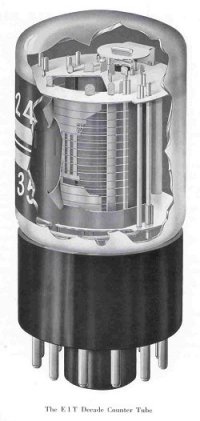

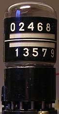 The E1T is a remarkable tube. In the first place it is a miniature cathode ray tube with a Pierce electron gun, two deflection plates and a fluorescent screen. When the voltage on the deflection plates is varied, the electron beam scans over the fluorescent screen lighting one of the green windows next to the numbers. But it is more than just an indicator device such as a nixie or numitron tube. The E1T is not only an indicator, it is also a counter! Without the need for external active components it can count pulses at a rate up to 40 kHz, while counting rates up to 1 MHz have been demonstrated under laboratory conditions. So in modern day language the tube contains a memory of 3.5 bits. The memory is realized in a very clever way. The Philips Researchers placed a screen with slotted apertures in the path of the electron beam just in front of the fluorescent screen. When the beam passes a slot, one of the numbers is illuminated, though only very little current flows though the aperture. However, when the beam hits the screen in between two slots, the full bundle current is now carried by the screen. With a simple feedback circuit this current is used to adjust the voltage on the deflection plates so that the beam stays ōlockedö in one of the slot positions. By applying a short AC pulse of well defined amplitude to one of the deflection plates, the beam is forced to the next stable position. All in all a very clever construction, but not an easy one to manufacture.
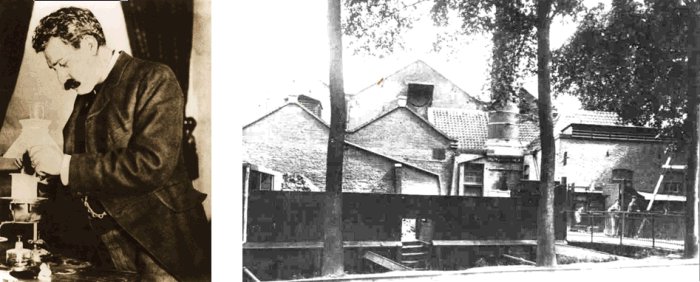
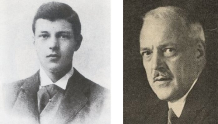
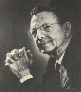
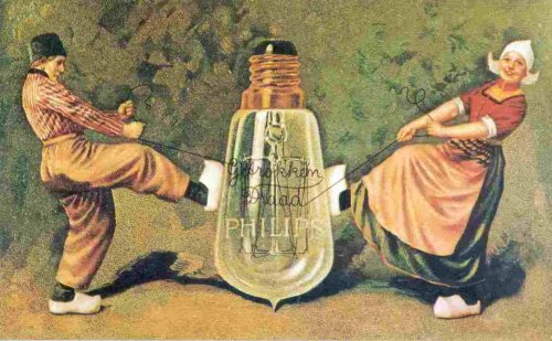
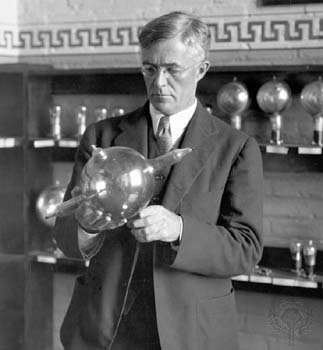
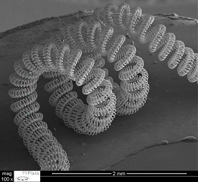
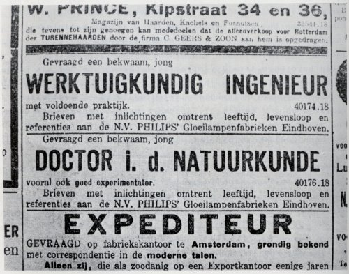
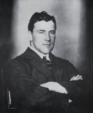
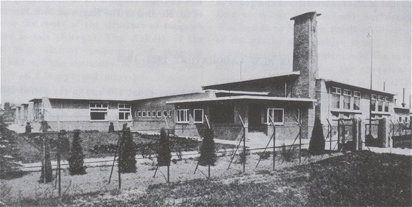
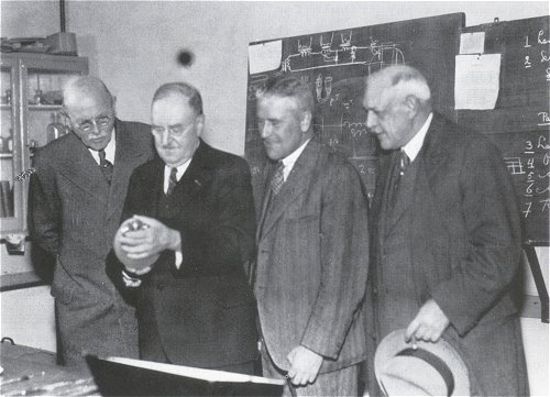
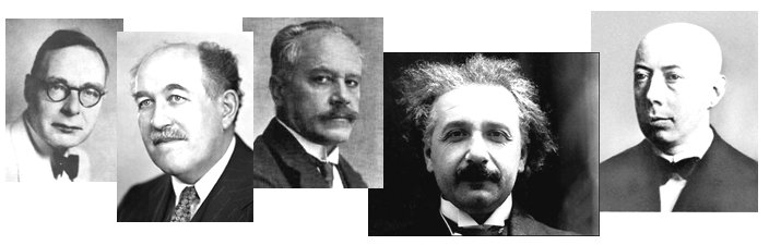
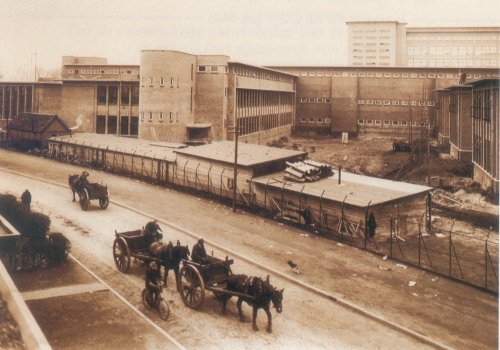

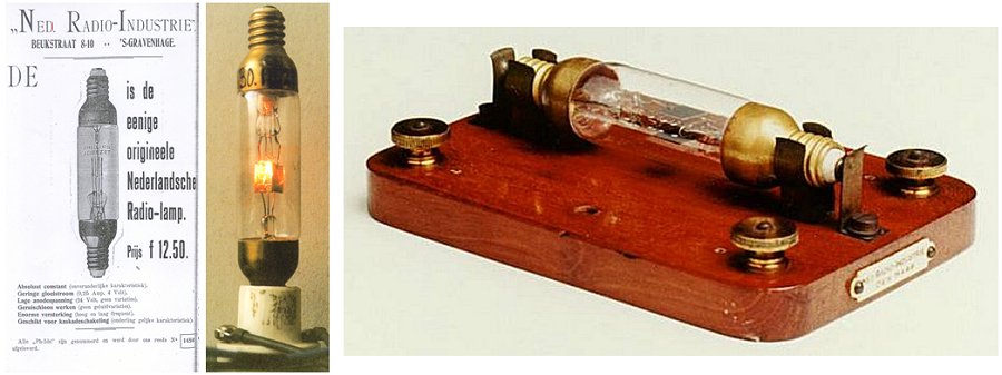
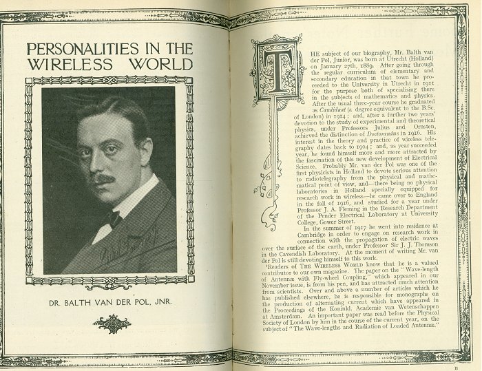
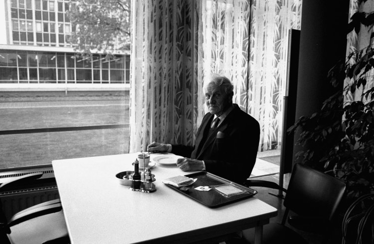
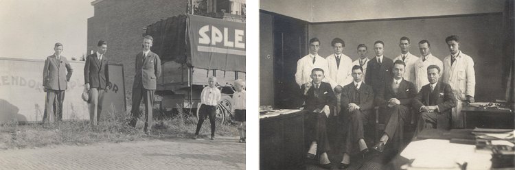
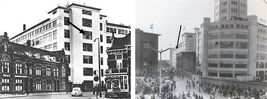
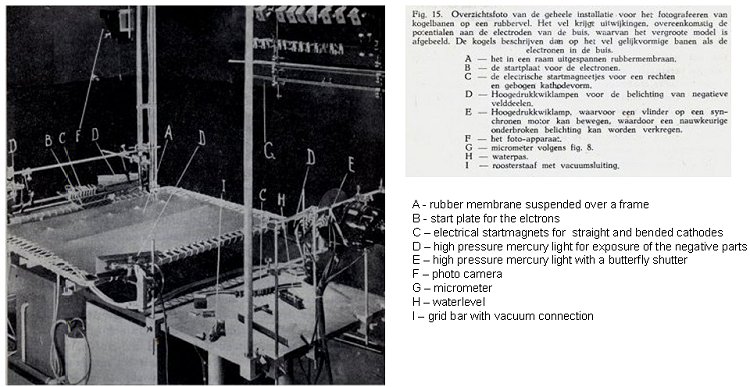
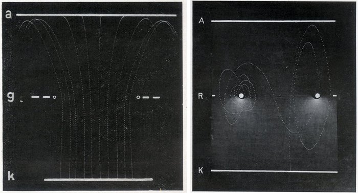
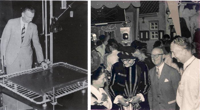
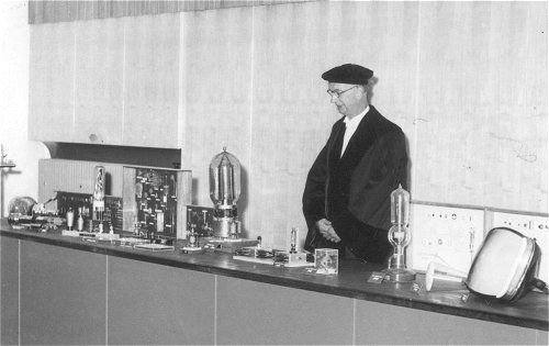
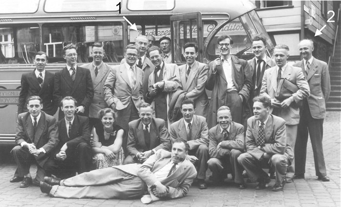
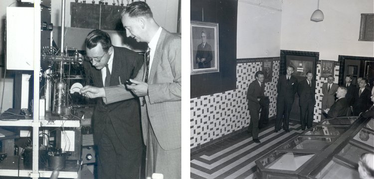


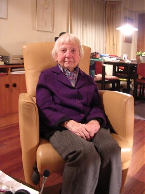
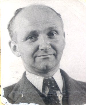
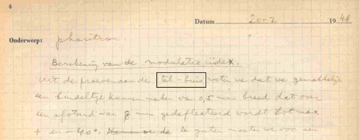
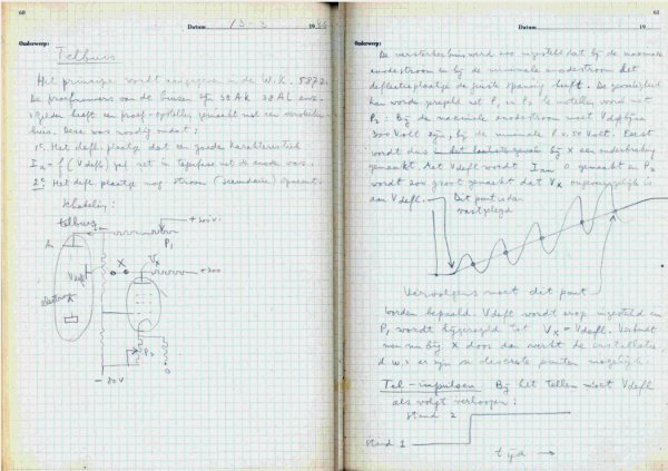
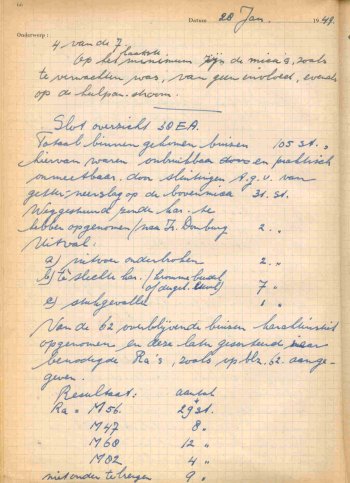
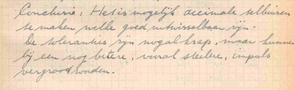
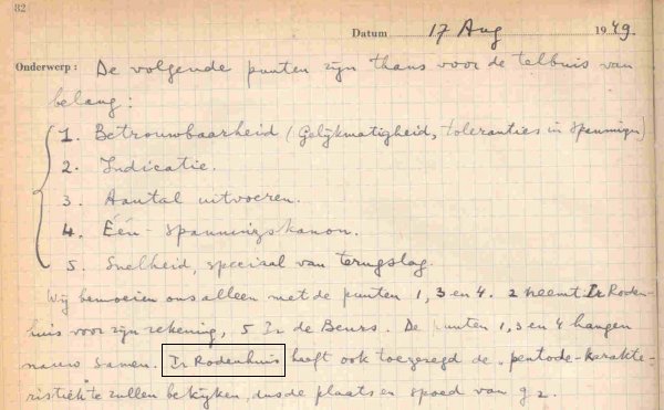
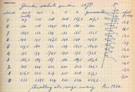
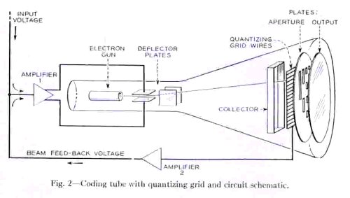
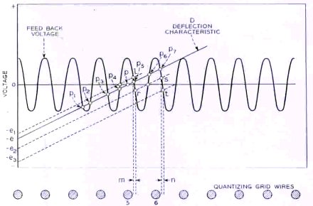
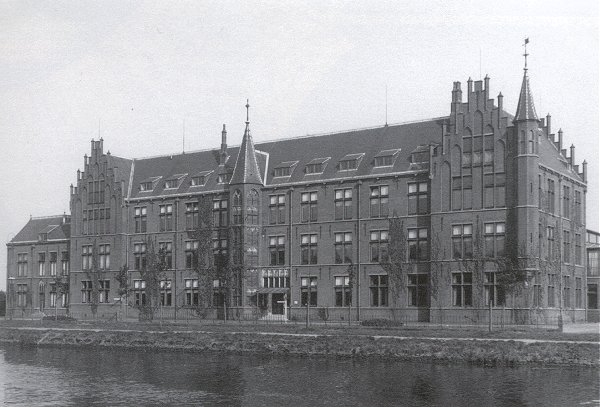


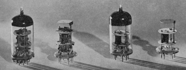

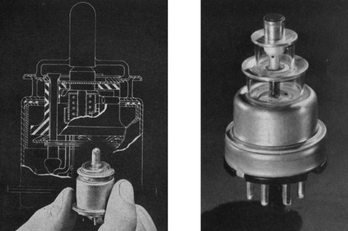
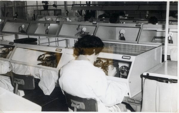
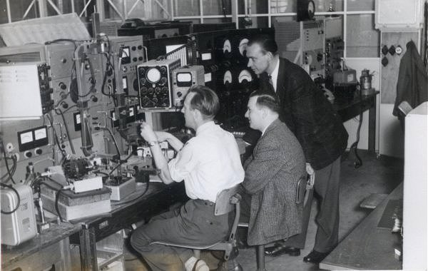
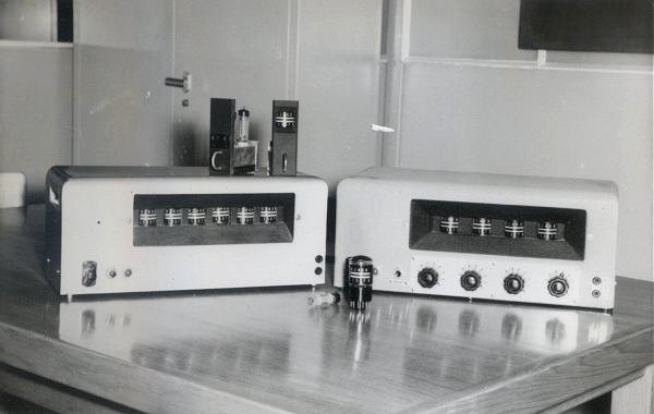
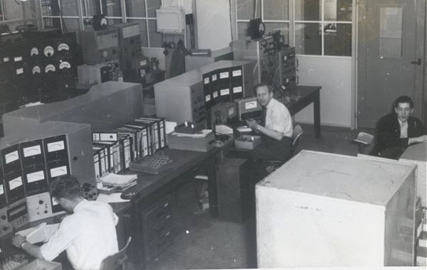
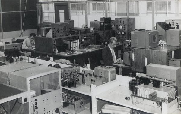
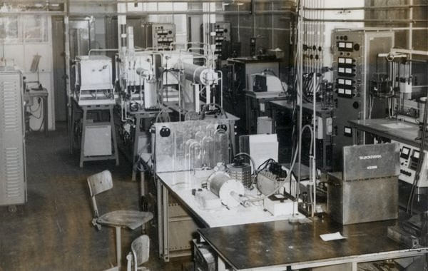

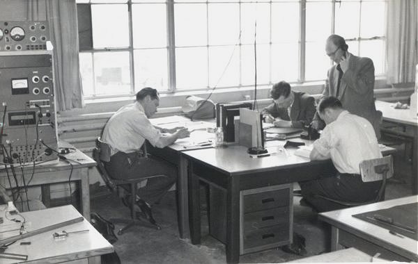
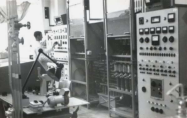
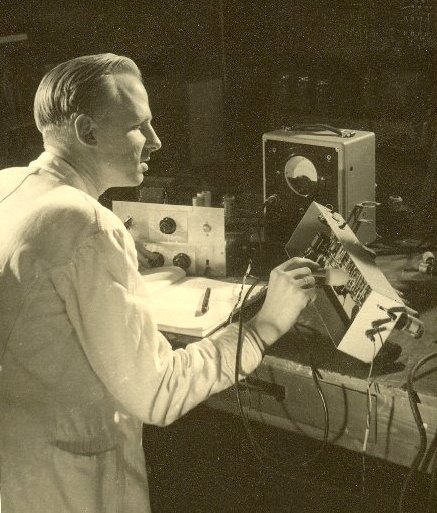
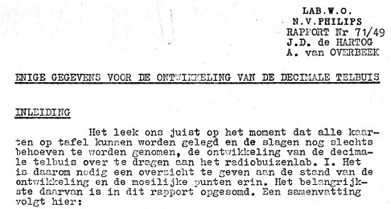
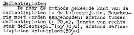
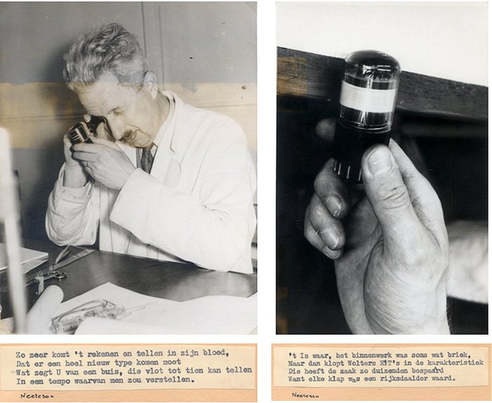
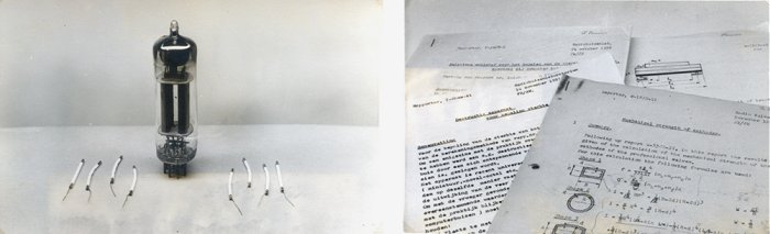
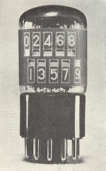
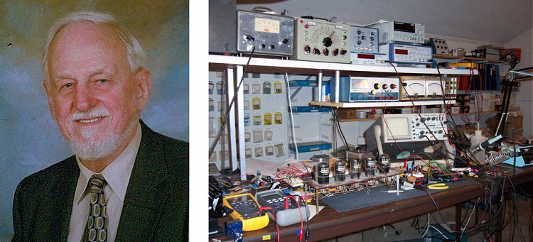

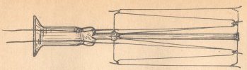
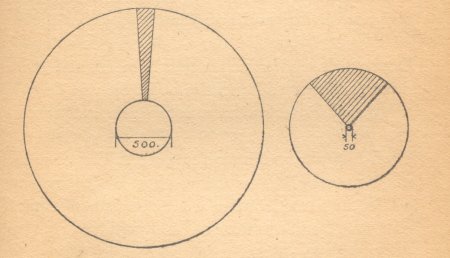

 Fig. 3a shows a cross-section of the decade counter tube, whilst fig. 3b
shows the diagramic representation which will be used in circuit
diagrams. The cathode is of the conventional type as used in receiving
valves, apart from the fact that it emits electrons from on side only of
its rectangular cross-section. A control grid (g1), four rod-shaped
focussing electrodes (p1, p2) and an accelerating electrode (g2), together
with the cathode, form the electron gun. This has been so designed that
the cross-section of the electron bean thus obtained is not circular but
ribbon-shaped. A ribbon-shaped electron beam has the following advantages:
Fig. 3a shows a cross-section of the decade counter tube, whilst fig. 3b
shows the diagramic representation which will be used in circuit
diagrams. The cathode is of the conventional type as used in receiving
valves, apart from the fact that it emits electrons from on side only of
its rectangular cross-section. A control grid (g1), four rod-shaped
focussing electrodes (p1, p2) and an accelerating electrode (g2), together
with the cathode, form the electron gun. This has been so designed that
the cross-section of the electron bean thus obtained is not circular but
ribbon-shaped. A ribbon-shaped electron beam has the following advantages:
 Advantage is taken of this principle for fixing the position of the beam
in the counter tube. In this case too, the anode a2 and the deflection
electrode D' (i.e. the one nearest to the figure 0) are connected to
direct voltage source Vb via a common resistor Ra2 (fig. 5); the potential
of D and a2 is denoted by vDa2. The straight line I of fig. 4b is now,
however, replaced by the undulated curve I of fig. 6; the way this curve
is obtained will be shown presently. This curve is intersected 19 times by
the resistance line II. Each of these points of intersection corresponds
to a condition of equilibrium - although only ten points of intersection
numbered from 0 to 9 represent stable positions. From this it may be seen
that the position of the beam indicated diagrammatically in fig. 3a is one
of its stable positions, i.e., passing partly through a slot and impinging
partly on the metal on the left of this slot: in fact, when the beam is
deflected further to the left the current initially increases, in
accordance with characteristic I near the points of intersection 0...9
(fig. 6).
Advantage is taken of this principle for fixing the position of the beam
in the counter tube. In this case too, the anode a2 and the deflection
electrode D' (i.e. the one nearest to the figure 0) are connected to
direct voltage source Vb via a common resistor Ra2 (fig. 5); the potential
of D and a2 is denoted by vDa2. The straight line I of fig. 4b is now,
however, replaced by the undulated curve I of fig. 6; the way this curve
is obtained will be shown presently. This curve is intersected 19 times by
the resistance line II. Each of these points of intersection corresponds
to a condition of equilibrium - although only ten points of intersection
numbered from 0 to 9 represent stable positions. From this it may be seen
that the position of the beam indicated diagrammatically in fig. 3a is one
of its stable positions, i.e., passing partly through a slot and impinging
partly on the metal on the left of this slot: in fact, when the beam is
deflected further to the left the current initially increases, in
accordance with characteristic I near the points of intersection 0...9
(fig. 6).
 In fig. 7a a slotted electrode and an anode have been drawn as flat
planes. It is assumed that the ten slots have the same dimensions and are
equidistant and that the thickness of the ribbon-shaped beam exceeds the
width of the slots and is less than the width of the spaces between the slots.
In fig. 7a a slotted electrode and an anode have been drawn as flat
planes. It is assumed that the ten slots have the same dimensions and are
equidistant and that the thickness of the ribbon-shaped beam exceeds the
width of the slots and is less than the width of the spaces between the slots.
 As a starting point it is assumed that the beam occupies one of its stable
positions, for example position 0. If a positive pulse is now applied to
the left deflection electrode, so that vD is temporarily increased, the
beam will tend to move to the left (fig. 3a); the number of electrons
passing through slot 0 decreases, i.e. the anode current ia2 is reduced. If
no stray capacitances were present, the decrease of ia2 would result
in a rise of the potential of the anode and of the right deflection electrode
connected to it, and this increase of vD',a2 would counteract the deflection
to the left, so that the beam would be retained at position 0.
As a starting point it is assumed that the beam occupies one of its stable
positions, for example position 0. If a positive pulse is now applied to
the left deflection electrode, so that vD is temporarily increased, the
beam will tend to move to the left (fig. 3a); the number of electrons
passing through slot 0 decreases, i.e. the anode current ia2 is reduced. If
no stray capacitances were present, the decrease of ia2 would result
in a rise of the potential of the anode and of the right deflection electrode
connected to it, and this increase of vD',a2 would counteract the deflection
to the left, so that the beam would be retained at position 0.
 In an electronic tube, whether rectifier (ōvalveö), amplifier, transmitting tube, or cathode-ray tube, electrons move in vacuum under the influence of electric fields originating from their fellow electrons (space charge) and from electrodes, or of magnetic fields originating from magnets or coils. But how does one get these electrons? Inside a metal, electrons are more or less free to move about but they are held in the metal by an attractive potential. How can we get them out? There are a number of ways. One can apply a very strong external electric field and pull them out. This is really possible and the phenomenon is known as cold emission; it has been applied in a few special tubes but is of limited applicability. In other cases, cold emission is rather a nuisance: it may lead to electrical discharges in high-voltage tubes (for instance, X-ray tubes) in places where we do not want any electric discharge.
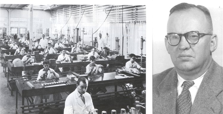
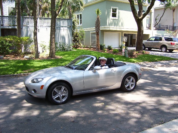